
Flowchart-based control system including automatic downtime and cycle time analysis

a flowchart and control system technology, applied in the field of flowchart-based programming and control systems, can solve the problem that systems generally do not track the operational status of the process

Inactive Publication Date: 2005-03-08
PHOENIX CONTACT SERVICES
View PDF2 Cites 6 Cited by
  • Summary
  • Abstract
  • Description
  • Claims
  • Application Information

AI Technical Summary

Benefits of technology

A flowchart-based programming and control system includes a computer with a processor, memory, and display. A device is connected to the computer and is associated with a process. A flowcharting module run by the computer generates and edits flowchart source code that includes flowchart blocks and that contains logic for operating the device to further the process. First and second flowchart blocks change an operational state of the process. A reason code module associated with the flowcharting module assigns reason codes to the status of the process using a special type of action or decision block. The flowchart module compiles the flowchart source code into flowchart object code. A flowchart run-time engine module associated with the computer executes the flowchart object code to control the process. The flowchart object code generates the reason codes during execution of the associated flowchart blocks in the flowchart object code. A performance analysis module and a charting module record and graphically represent the operational state of the process over time.

Problems solved by technology

While conventional flowchart systems typically display the current location of control within the flowchart, these systems generally do not track the operational status of the process over time.

Method used


Image

  • Flowchart-based control system including automatic downtime and cycle time analysis
  • Flowchart-based control system including automatic downtime and cycle time analysis
  • Flowchart-based control system including automatic downtime and cycle time analysis

Examples


Embodiment Construction

The ensuing detailed description provides preferred exemplary embodiments only and is not intended to limit the scope, applicability or configuration of the present invention. Rather, the ensuing detailed description of the preferred exemplary embodiments will provide those skilled in the art with an enabling description for implementing the preferred exemplary embodiments of the present invention. It being understood that various changes may be made in the function and arrangement of the elements without departing from the spirit and scope of the invention as set forth in the appended claims.

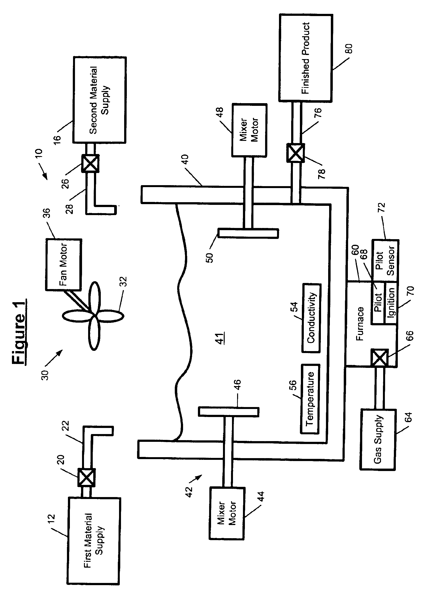
Referring now to FIG. 1, an exemplary process 10 will be employed to illustrate the invention. The process 10 heats and mixes two materials until their conductivity reaches a pre-selected conductivity. Then, the process delivers the materials to a holding tank. The process 10 includes a supply 12 for a first material and a supply 16 for a second material. A solenoid valve 20 is positioned in li...


PUM


Abstract

A flowchart-based programming and control system includes a computer with a processor, memory, and display. A device is connected to the computer and is associated with a process. A flowcharting module generates and edits flowchart source code that includes flowchart blocks and that contains logic for operating the device. First and second flowchart blocks assign an operational state of the process. A reason code module associated with the flowcharting module assigns first and second reason codes to the first and second flowchart blocks. The flowchart module compiles the flowchart source code into flowchart object code. A flowchart run-time engine module executes the flowchart object code to control the process. The flowchart object code generates the first and second reason codes during execution of the first and second flowchart blocks. A performance analysis module and a charting module record and graphically represent the operational state of the process over time.

Description

BACKGROUND AND SUMMARY OF THE INVENTIONThe present invention relates to programming and control systems. More particularly, this invention relates to flowchart-based programming and control systems that automatically capture operational modes of a process for downtime and cycle time analysis.Programming and control systems are generally used for controlling processes that involve devices such as relays, solenoids, motors, valves, switches, and other electrical and electromechanical devices. The processes that are controlled include machining, drilling, welding, spraying paint, mixing materials, assembling parts, handling materials, etc.Conventional programming and control systems generally employed ladder diagrams and relay ladder logic (RLL) to control the operation of the devices associated with the processes. In practice, however, programmers tend to use a flowchart to initially define the operation of the devices in the process. Then, the programmers manually translated the flow...

Claims


Application Information

Patent Timeline
Patent Type & Authority Patents(United States)
IPC IPC(8): G06F9/44G05B19/05
CPCG05B19/056G05B2219/13122
Inventor MCMILLAN, ANDREW H.GASIOREK, JOSEPHHARKAWAY, THOMAS
Owner PHOENIX CONTACT SERVICES
Learn More