
System and method for identifying executable diagnostic routines using machine information and diagnostic information in a computer system

a computer system and machine information technology, applied in the field of computer systems, can solve the problems of unable to prevent the diagnostic routine for joysticks, and typically not including diagnostic packages, so as to minimize the development effort and test cycle, and easily offer additional systems. , the effect of minimizing the development effort and testing cycl

Inactive Publication Date: 2005-03-08
DELL PROD LP
View PDF13 Cites 53 Cited by
  • Summary
  • Abstract
  • Description
  • Claims
  • Application Information

AI Technical Summary

Benefits of technology

A principal advantage of this embodiment is that an entire suite of diagnostic routines may be installed on each computer system offered by a computer manufacturer while only supported diagnostic routines may be made selectable for execution on a particular system based on certain characteristics of that system. In this way, the process of installing diagnostic routines may be substantially similar or even identical for each system that a computer manufacturer offers. In addition, this embodiment may advantageously allow a computer manufacturer to change the set of supported diagnostic routines on a system or systems while minimizing the development effort and test cycle for each change. The embodiment may also advantageously allow a computer manufacturer to easily offer additional systems or test support with minimal development effort and testing.

Problems solved by technology

The diagnostic package, however, may not include platform or operating system specific information that may be used to identify the diagnostic routines that are executable on a given platform and / or operating system.
Diagnostic packages typically do not include a method for restricting the display and execution of a diagnostic routine for a component which a computer manufacturer does not wish to support.
Thus, in the example above, the computer manufacturer may not be able to prevent the diagnostic routine for the joystick from being displayed and executed using only the diagnostic package.
Such a program would require a costly and inefficient development effort and testing process for each platform sold by a manufacturer.

Method used


Image

  • System and method for identifying executable diagnostic routines using machine information and diagnostic information in a computer system
  • System and method for identifying executable diagnostic routines using machine information and diagnostic information in a computer system
  • System and method for identifying executable diagnostic routines using machine information and diagnostic information in a computer system

Examples


Embodiment Construction

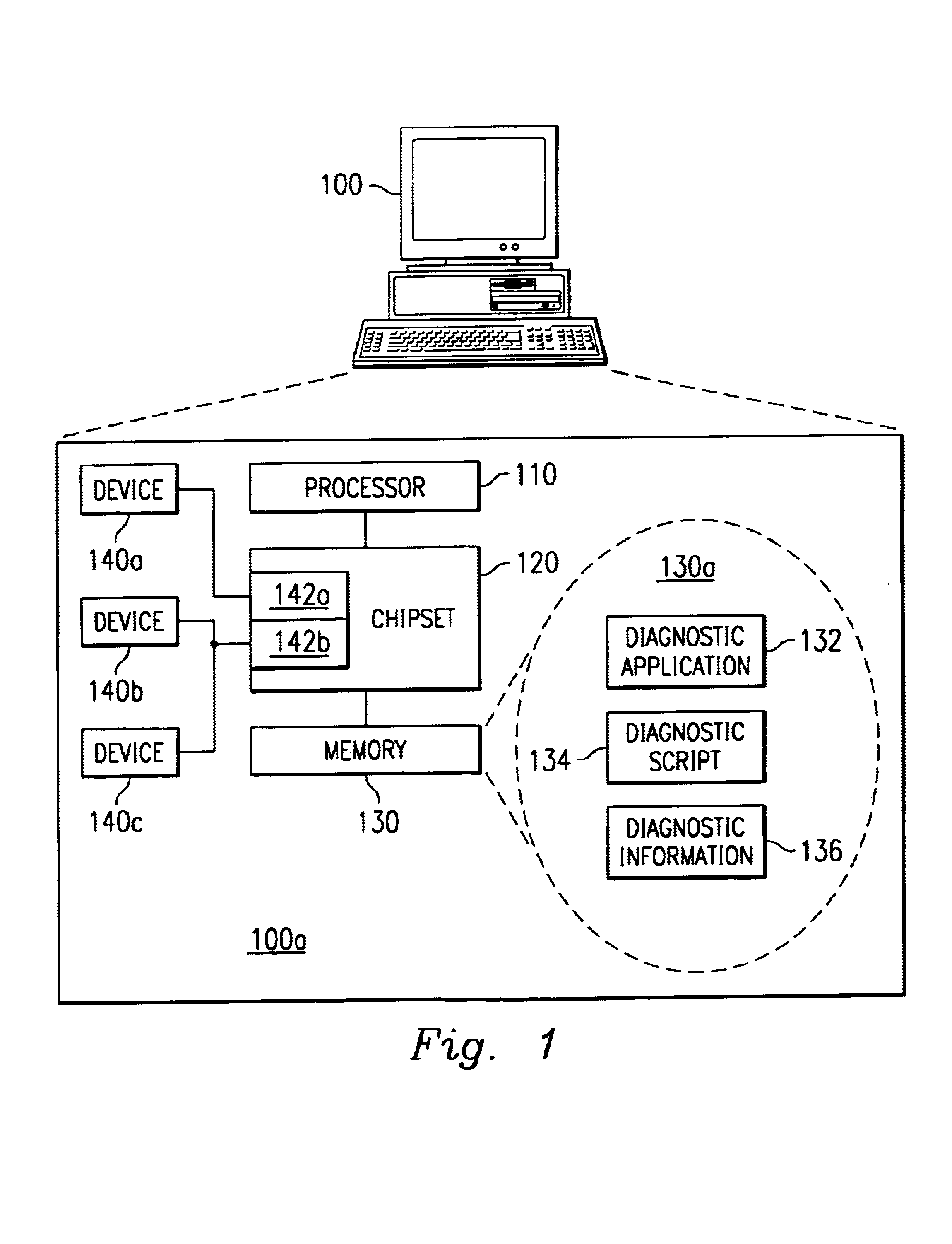
FIG. 1 is a diagram illustrating an embodiment of a computer system. FIG. 1 depicts a computer system 100. Computer system 100 includes a processor 110, a chipset 120, a memory 130, and a plurality of devices 140a, 140b, and 140c. Device 140a may be coupled to a port 142a. Devices 140b and 140c may be coupled to a shared bus 142b. A portion of memory 130a within memory 130 may include a diagnostic application 132, a diagnostic script 134, and a provided amount of diagnostic information 136. Diagnostic application 132 includes a plurality of diagnostic routines.

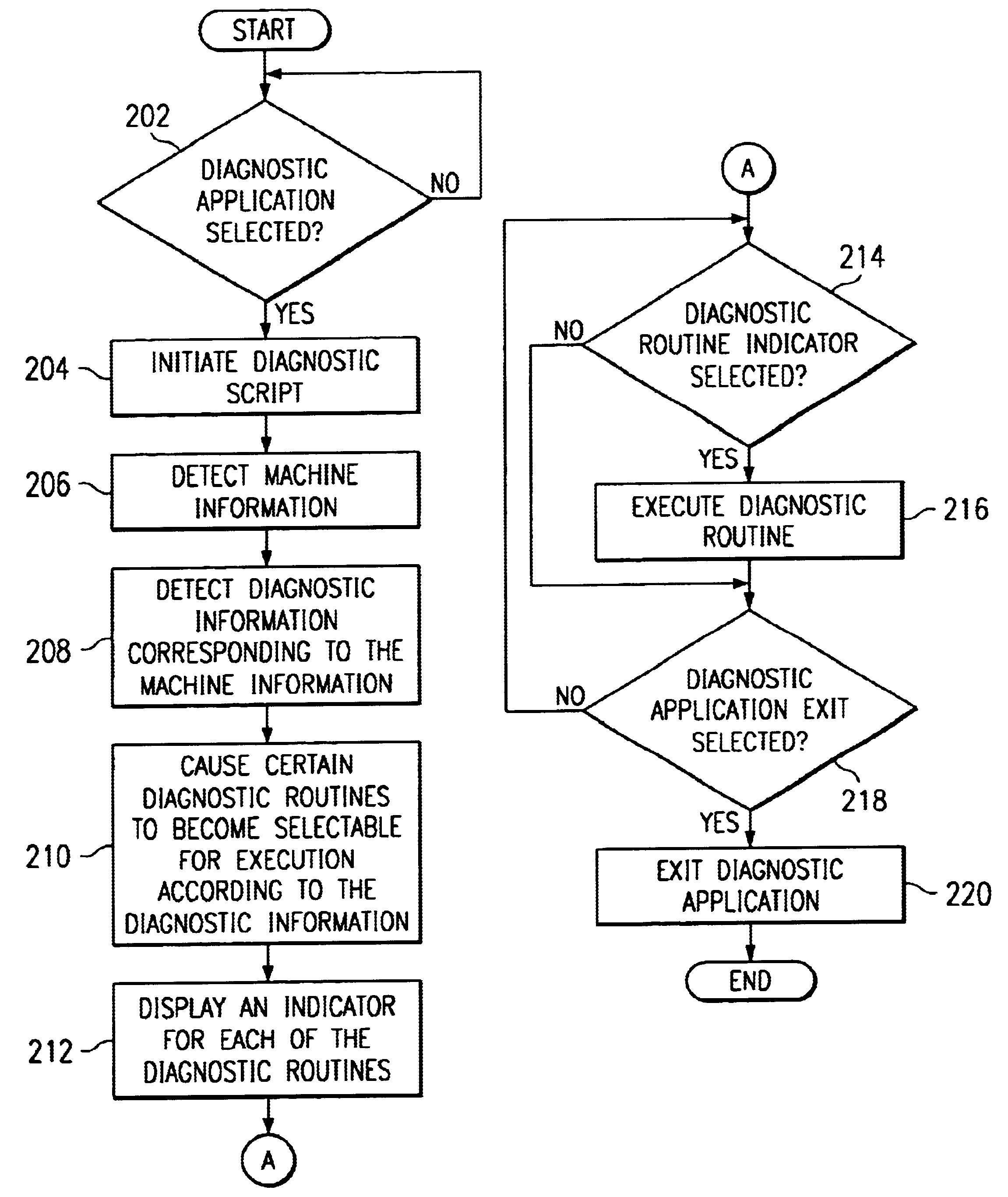
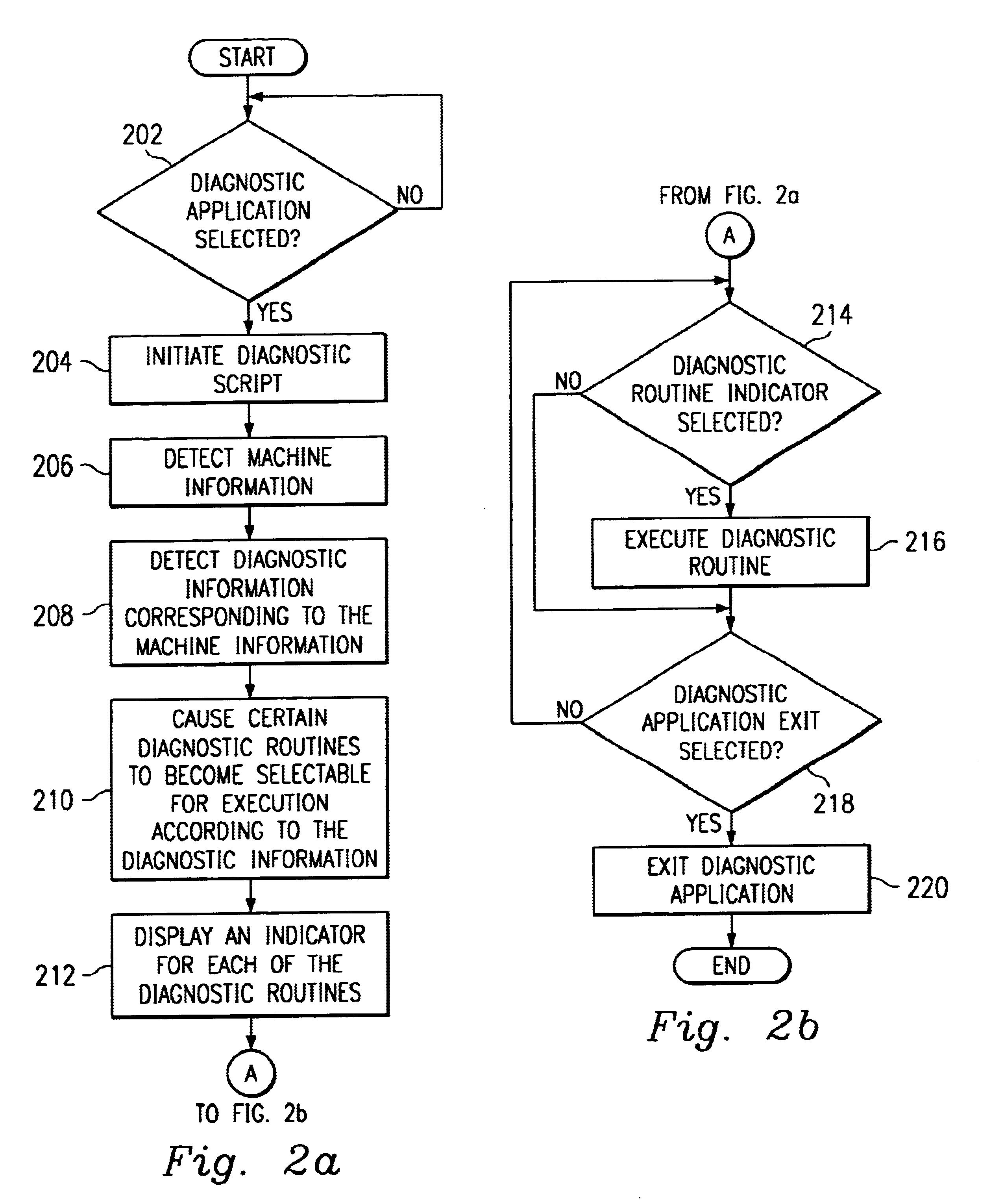
In computer system 100, diagnostic script 134 may be executed by computer system 100 and may identify a set of diagnostic routines within diagnostic application 132 that may be selected for execution by computer system 100. To do so, diagnostic script 134 may cause machine information corresponding to computer system 100 to be read. The machine information may include an operating system type and a machine type. The operating ...


PUM


Abstract

A system and method for identifying executable diagnostic routines using machine information and diagnostic information in a computer system is provided. The method includes detecting machine information, detecting diagnostic information corresponding to the machine information, and causing one of a plurality of diagnostic routines to be selectable for execution according to the diagnostic information.

Description

BACKGROUNDThe disclosures herein relate generally to computer systems, and more particularly, to a system and method for identifying executable diagnostic routines using machine information and diagnostic information in a computer system.A computer system may include a diagnostic package with a set of diagnostic routines that may be executed to test components in the system. The manufacturer of the computer system may purchase a diagnostic package that includes a set of diagnostic routines from a third party vendor. The diagnostic package, however, may not include platform or operating system specific information that may be used to identify the diagnostic routines that are executable on a given platform and / or operating system.A computer manufacturer may wish to support only certain devices on certain platforms and / or operating systems. For example, a computer manufacturer may wish to sell a computer system that does not support joysticks. The diagnostic package installed by the co...

Claims


Application Information

Patent Timeline
IPC IPC(8): G06F11/00
CPCG06F11/2289
Inventor BRUNDRIDGE, MICHAEL A.JIMENEZ, JAVIER L.
Owner DELL PROD LP
Learn More