
Self-contained devices for detecting biological contaminants

a technology of self-contained devices and biological contaminants, which is applied in the direction of laboratory glassware, analysis material containers, instruments, etc., can solve the problems of contaminant finding on equipment or other surfaces, requiring expensive and complicated equipment, and contaminant testing may be time-consuming and labor-intensiv

Inactive Publication Date: 2005-03-08
BIOCONTROL SYST
View PDF15 Cites 42 Cited by
  • Summary
  • Abstract
  • Description
  • Claims
  • Application Information

AI Technical Summary

Benefits of technology

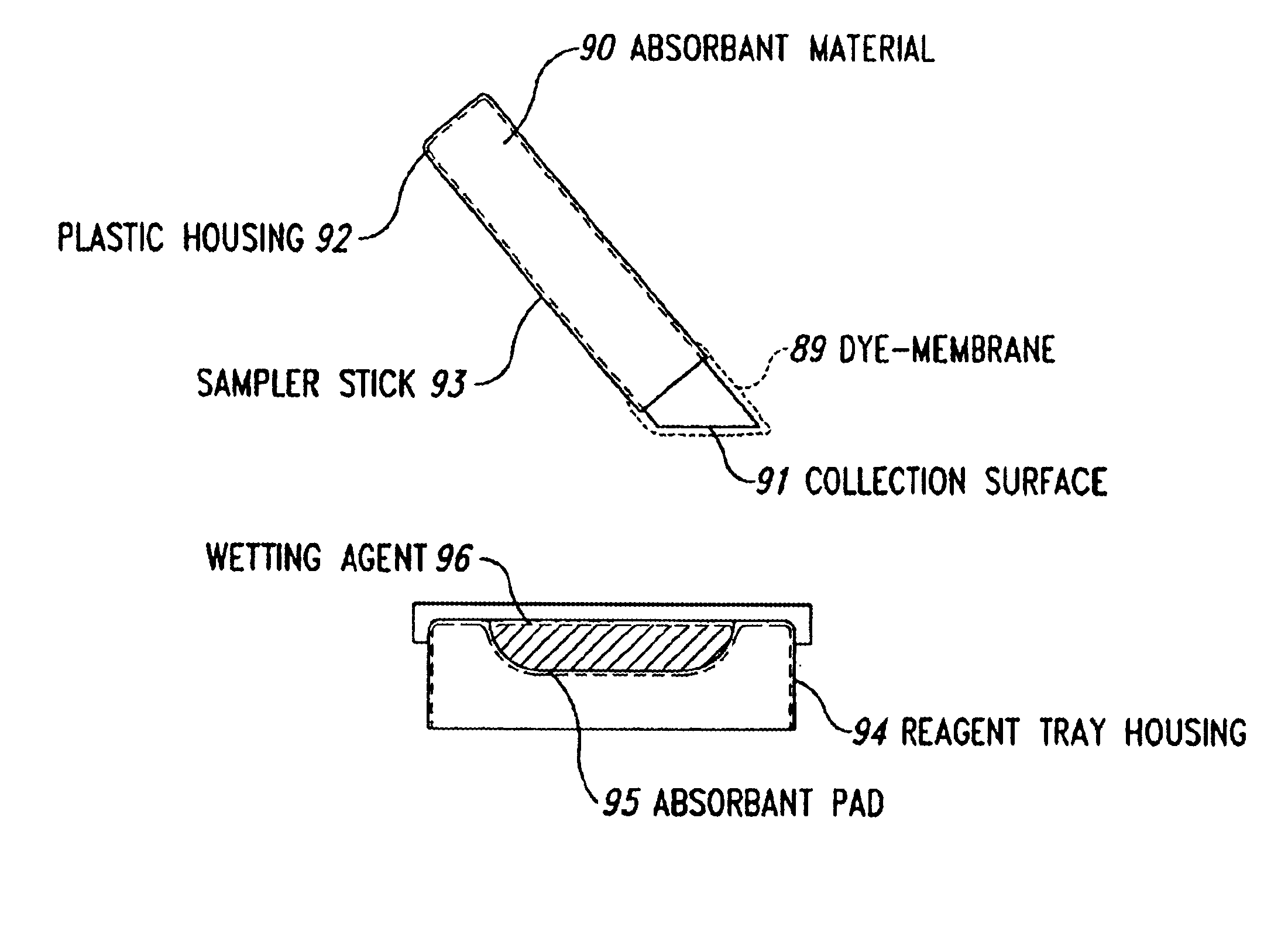
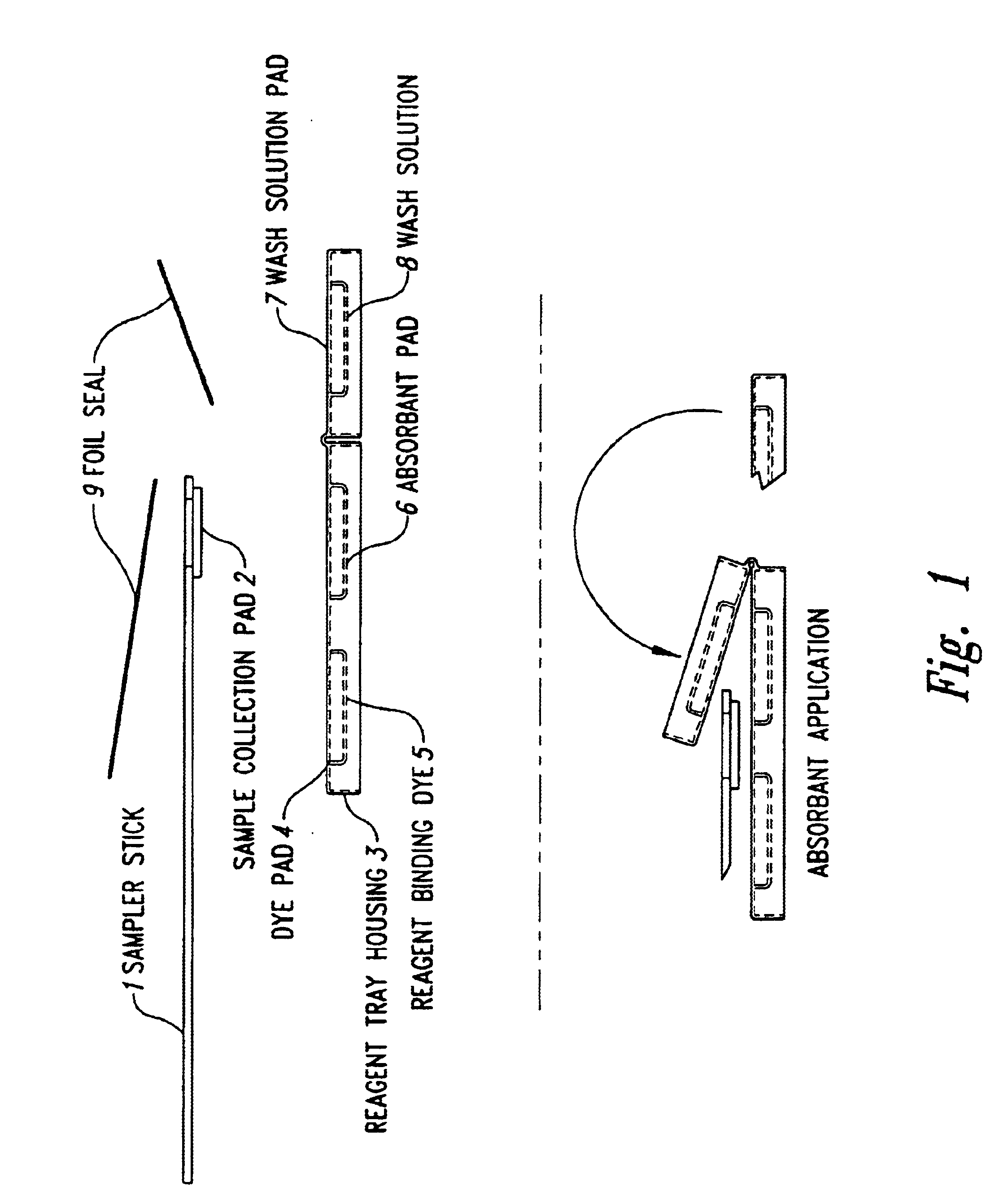
In one embodiment the device comprises a reagent housing comprising an absorbent material, wherein one of the absorbent materials is saturated with the wash solution, and the other of the absorbent materials is unsaturated, wherein unbound dye from a sampler collection surface disposed there between is washed by the flow of the wash solution from the saturated absorbent material to unsaturated absorbent material. In addition, the dye may be transported by the wash solution to the target mater

Problems solved by technology

Such contaminants may be found on equipment or other surfaces used in environments including food processing plants, hospitals, veterinary offices, and restaurants when a thorough cleaning has not been performed.
Tests for these materials are not only time consuming but they also typically require the use of expensive and complicated equipment.
Thus, routine testing of surfaces or equipment directly for bacteria or viruses is not practical in settings in which the testing is done by non-technical personnel and rapid results are demanded.
The presence of significant levels of ATP on a surface indicates that cleaning was incomplete and that bacteria may be present.
However, detecting ATP suffers from certain limitations that restrict its utility, in that it involves the use of a relatively expensive instrument and may involve transporting samples to a central laboratory.
Unfortunately, many examples of current methods for protein determination, which can serve as an indicator of a contaminated surface involve on-site reagent preparation due to stability problems, along with multiple transfer steps, incubation periods, and / or involve highly subjective color changes which make interpretation difficult, and / or require the use of complex instrumentation or specially trained personnel.
However, all of the aforementioned devices suffer from the same drawbacks noted above.

Method used


Image

  • Self-contained devices for detecting biological contaminants
  • Self-contained devices for detecting biological contaminants
  • Self-contained devices for detecting biological contaminants

Examples


example 1

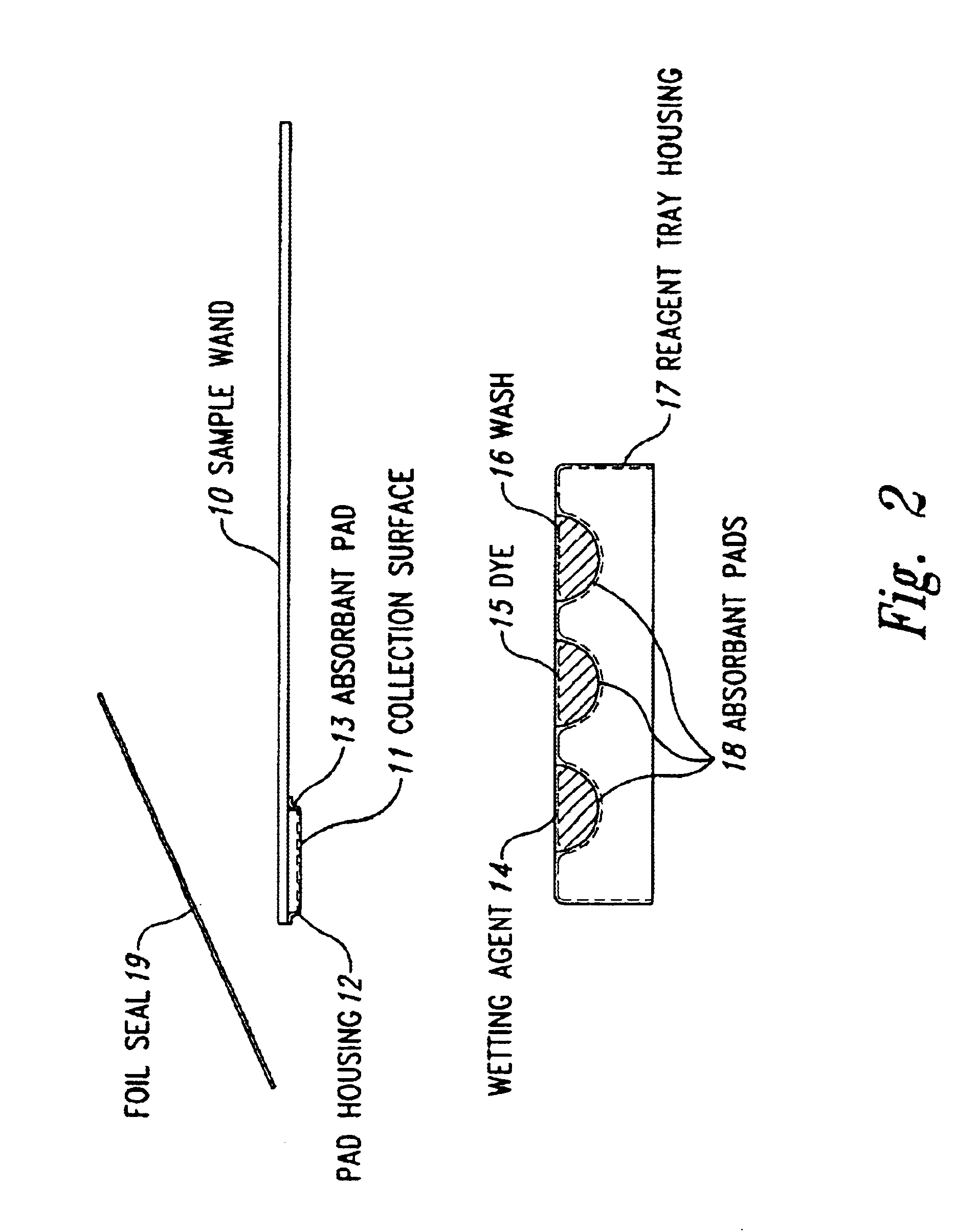
Exemplary devices were constructed as generally described in FIG. 2 and used with a precipitating dye (Ponceau 5) and a frequency shift dye (a colloidal Coomassie Blue dye, Gelcode®) and used to test food surfaces soiled with milk, cheese, roast beef, turkey, or tomato. The surfaces were also tested with a food industry-accepted means of measuring surface contamination based on ATP detection (LIGHTNING, produced by IDEXX Laboratories, Westbrook, Me.)(used according to manufacturer's instructions) as well as the protein detection devices described for this invention. As indicated, two different embodiments of the present invention were used. One with Ponceau-S as the protein-binding dye, and one with Gelcode®—a colloidal Coomassie blue dye.

Stainless steel surfaces were smeared with the indicated food materials. For each test, a sample was obtained from the surface by swabbing with the moistened sampler collection surface of a sampler from the particular device. “Dirty” indicates that...

example 2

An exemplary device constructed as generally described in FIG. 6 and containing 2 ml Pierce Gelcode® dye was used in a test to determine detection sensitivity of the device. Presence of protein was detected using qualitative visual reading and by reading the optical density (OD) at 595 nm, with the reported OD being the mean of two readings.

Bovine serum albumin (BSA) at various concentrations was dried on clean 4″×4′ stainless steel coupons. For each sample tested, the pre-moistened swab portion of a device was swiped over the coupon surface with firm pressure to collect the sample. The swab was inserted into the housing, and the dye reservoir bulb snapped to the side to deliver the dye into the lower read chamber. A visual interpretation is then made, followed by transfer from the read chamber to a disposable cuvette for reading at 595 nm. The results are shown in Table 2.

SampleO.D.Visual InterpretationNegative control (PBS)0.0006NegativeBSA, 5 μg / test3.3800+ + + +BSA, 50 μg / test1....

example 3

An exemplary device as in Example 2 was used in a comparison test of biological contamination with the Konica Hygiene Monitoring Kit. The Konica kit was utilized according to manufacturer's instructions with reading after 10 minutes at room temperature. The exemplary device was utilized as follows.

Various different sources of protein were dried upon clean 4˜×4˜ stainless steel coupons, which had been marked to divide each coupon into two equal parts. The exemplary device was used to collect the sample from the left side of the coupon surface. Following the Konica kit procedure, the corresponding right side of the coupon was sampled with the Konica swab. Visual interpretation for the exemplary device was made immediately upon activation. The Konica test was read at 10 minutes according to kit instructions. The stainless steel coupons were then washed with a mild detergent (Palmolive®) and water, and after drying, each side of the coupon was retested to detect any remaining contaminat...


PUM


Abstract

The present invention relates generally to self-contained devices and methods for detecting biological contaminants and, more particularly, to self-contained devices and methods for detecting biological contaminants in relevant settings including, for example, food processing plants, hospitals, medical offices, veterinary offices, and restaurants by using a device or methodology that includes a sampler component and dye component that binds to the biological material in a detectable fashion.

Description

TECHNICAL FIELDThe present invention relates generally to self-contained devices and methods for detecting biological contaminants and, more particularly, to self-contained devices and methods for detecting biological contaminants in relevant settings including food processing plants, hospitals, medical offices, veterinary offices, and restaurants by using a device or methodology that includes a sampler component and dye component that binds to the biological material in a detectable fashion.BACKGROUND OF THE INVENTIONThis invention relates to the field of testing for biological contaminants. Such contaminants may be found on equipment or other surfaces used in environments including food processing plants, hospitals, veterinary offices, and restaurants when a thorough cleaning has not been performed. Materials detected as indicators of contamination include, for example, viable bacterial cells, viruses, ATP, and protein. The ideal test for contamination would be effective, inexpens...

Claims


Application Information

Patent Timeline
IPC IPC(8): B01L3/00C12M1/28C12M1/26C12M1/30G01N33/543C12M1/34G01N1/00G01N1/02G01N33/52G01N33/68
CPCB01L3/50B01L3/5029B08B1/003B01L2400/0406G01N2001/028B01L2200/16B08B1/145
Inventor KELLY, TIM ALLENHASS, GEORGE MICHAELFELDSINE, PHILIP THOMAS
Owner BIOCONTROL SYST
Learn More