
Method and apparatus for remediation and prevention of fouling of recirculating water systems by detritus and other debris

a recirculating water system and detritus technology, applied in water cleaning, multi-stage water/sewage treatment, separation processes, etc., can solve the problems of allowing the process to continue unabated, detritus, golf balls, algae and all manner of debris accumulate, and the cost of recycled water is typically 40% of the cost, so as to effectively prevent future fouling and avoid the expense, the effect of significant financial savings for golf course operators

Inactive Publication Date: 2005-03-08
CRAWFORD III WILLIAM RANDALL
View PDF24 Cites 20 Cited by
  • Summary
  • Abstract
  • Description
  • Claims
  • Application Information

AI Technical Summary

Benefits of technology

The system effectively prevents fouling of recirculating water systems, reducing maintenance costs by up to 99% compared to traditional methods, allowing continuous operation without damaging the surroundings or disrupting golf course or fountain operations.

Problems solved by technology

The cost of recycled water is typically 40% of the cost of potable water available from a municipal water supply.
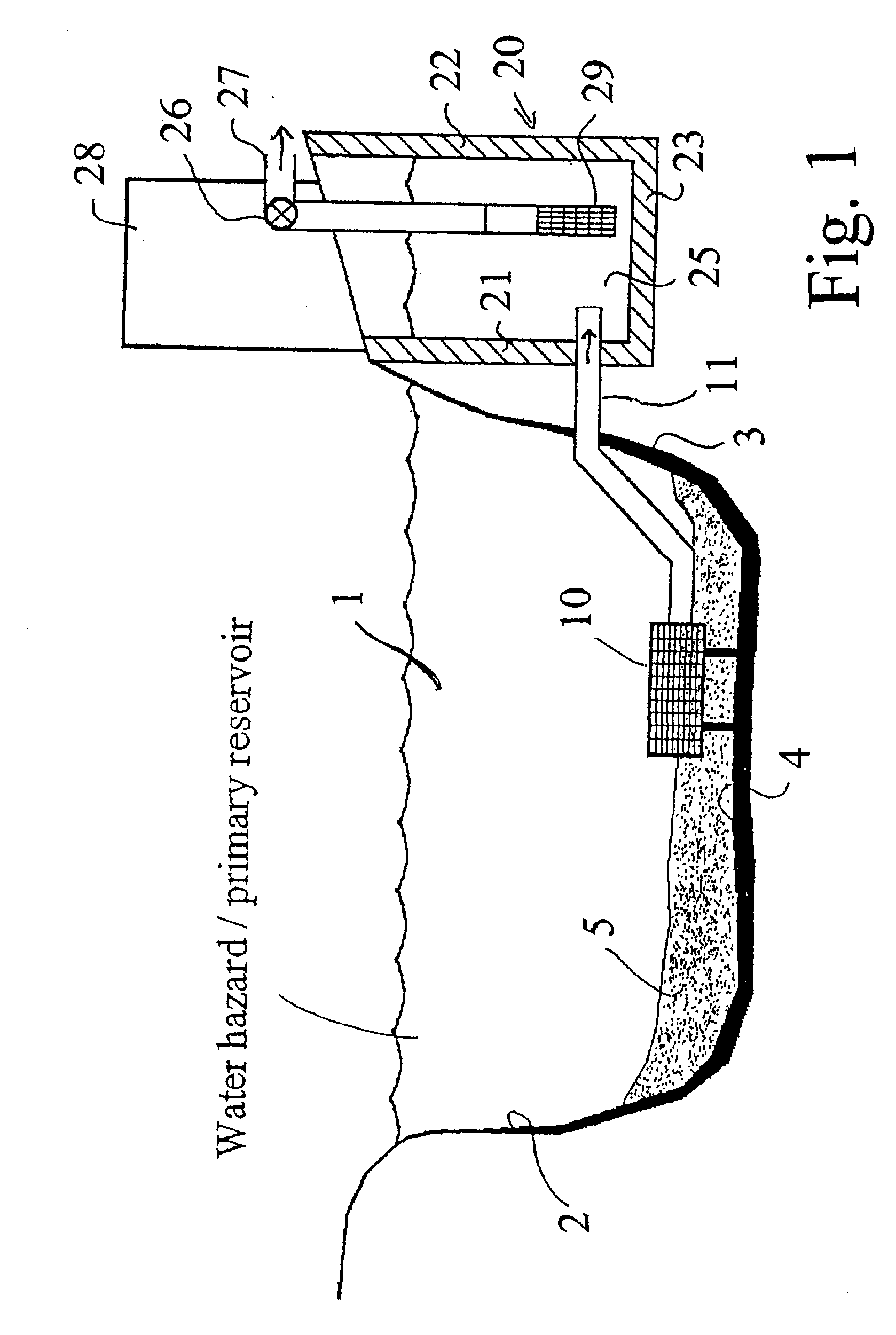
The problem with existing recirculating water systems for golf courses is that over time, detritus, golf balls, algae and all manner of debris accumulate in the water and on the bottom of the water hazard or lake that is used as the primary reservoir for the sprinkler system.
In addition, algae in many situations tends to collect around the grating used on typical existing water intakes.
The financial ramifications of allowing this process to continue unabated can be catastrophic.
For example, if a water hazard acting as a primary reservoir has to be cleaned, the prior art systems typically require the golf course operator to close down operation of the golf course and drain the water hazard acting as the primary reservoir.
During this process, it is not unusual for rather serious damage to be caused to the turf around the water hazard acting as the primary reservoir due to the access required by the rather heavy machines that must enter the drained water hazard.
In addition to these out-of-pocket expenses, the golf course operator often suffers the additional expense of shutting down the golf course as well as expense of replacing turf and vegetation that dies while the irrigation system is closed down.
Some golf courses may remain open by using the more expensive potable water (if available) and paying the increased cost.
In addition to the cost of cleaning a water hazard acting as a pimary reservoir for the irrigation system, additional expensive damage may be caused to the pumping system and sprinkling system by the unabated accumulation of detritus and other debris allowed to enter the pumping and sprinkling system.
In addition to the replacement cost of sprinkler heads, there are additional costs of turf and vegetation which dies as a result of fouled sprinkler heads.
A further complication is that some fouled sprinkler heads remain open and cause localized flooding.
Localized flooding can require shutdown of a portion of or the entire golf course.
Additional damage may be done to the large pumps utilized to supply water from the “wet wells” to the sprinkler system and to pumps transferring water from the primary reservoir into the “wet well” or secondary storage reservoir.
Another danger in those installations where pumps are used to transfer water from the water hazard / primary reservoir to the “wet well” is that the screens at the intake become clogged with algae and the pumps cavitate.
The cavitation can cause the pumps to burn out, requiring their replacement.
Many of the above problems described for typical golf course recirculating sprinkler systems are also experienced in systems which recirculate water in ornamental pools, water fountains, ponds and the like.

Method used


Image

  • Method and apparatus for remediation and prevention of fouling of recirculating water systems by detritus and other debris
  • Method and apparatus for remediation and prevention of fouling of recirculating water systems by detritus and other debris
  • Method and apparatus for remediation and prevention of fouling of recirculating water systems by detritus and other debris

Examples


Embodiment Construction

The invention may be “scaled up” dimensionally for larger projects, wherein a larger eductor, larger vacuum line, larger high pressure line are utilized with larger pumps and motors.

It is also within the scope of the invention to combine two or more pumps to drive a larger eductor in order to utilize a larger diameter suction line. A larger diameter suction line is able to remove larger amounts of the detritus and debris and / or larger diameter pieces of detritus and debris. FIG. 14 illustrates conceptually how eductor 240 is constructed with a 6 inch diameter vacuum line 260. The high pressure water intake line 270 could be either 5 or 6 inches in diameter. Water is pumped into intake line 270 by three pumps 271,272 and 273 whose outlet lines are joined by three-way close fitting 275 which itself connects directly to intake pressure line 270. In this embodiment, the operational pressure of each pump in psi is equalized to achieve the maximum efficiency of eductor 240.

FIG. 15 illustr...


PUM

PropertyMeasurementUnit
diameteraaaaaaaaaa
diameteraaaaaaaaaa
radiusaaaaaaaaaa

Abstract

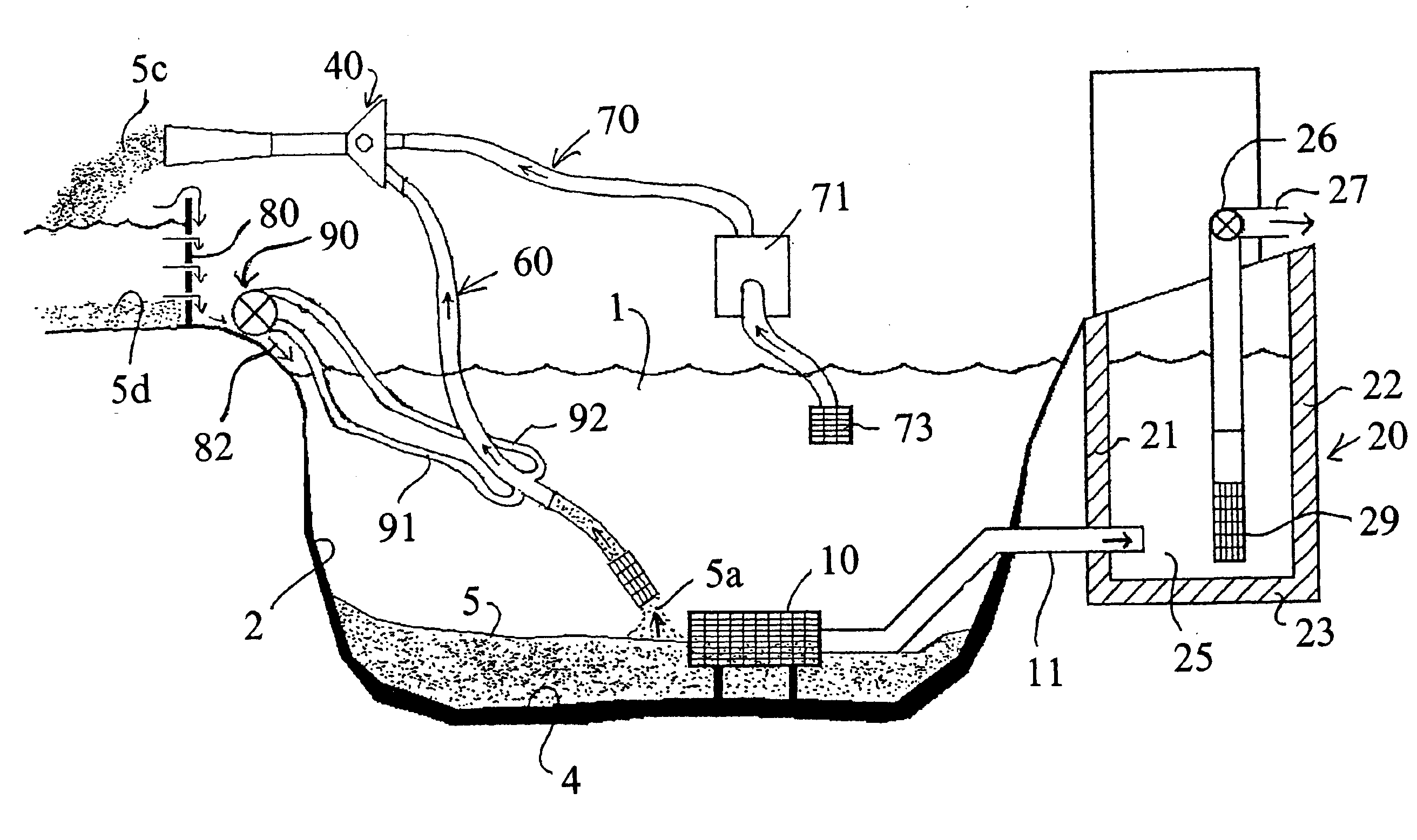
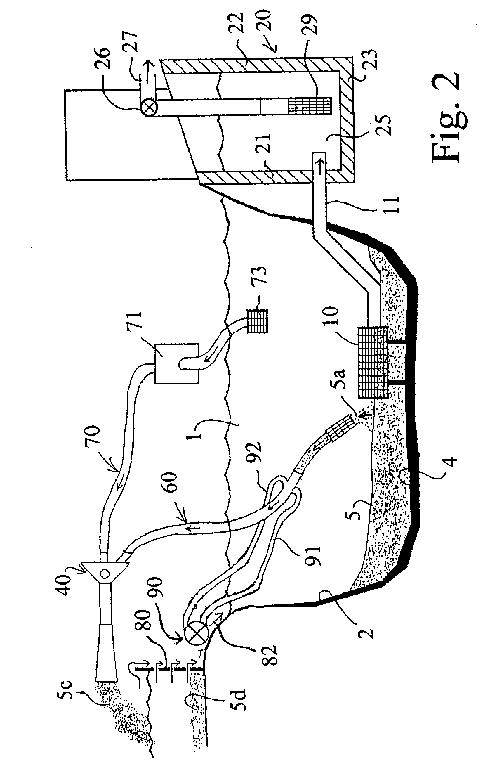
An apparatus and method are provided for removing accumulated underwater debris from a reservoir for a recirculating water system, such as used for a golf course sprinkler system. An eductor is provided which is driven by a high pressure water pump. The high pressure creates a vacuum which is utilized to actuate a vacuum line. The vacuum line is moved to and fro in the reservoir to entrain the debris from the reservoir in water and to carry the entrained debris to the eductor. The entrained debris is discharged from the eductor into a separator having a permeable membrane which traps the debris and allows the water to return to the reservoir. Various separators are provided. The eductor includes an adjustably mounted nozzle to adapt to different sized debris being removed from the reservoir.

Description

BACKGROUND AND BRIEF SUMMARY OF INVENTIONThe present invention relates generally to maintenance of large scale recirculating water systems. In particular, the present invention provides a method and apparatus for removal of accumulated sand, silt, detritus, algae and other debris from golf course recirculating water and irrigation systems. A related application of the invention is for maintenance of recirculating water systems used, for example, in ponds, water fountains and decorative pools.Typical golf course recirculating sprinkler systems will pump 750,000 to 2,500,000 gallons per night during the warm season through a system of 2,000 to 2,400 sprinkler heads. Most golf courses are designed so that lakes or water hazards are primary storage reservoirs for the sprinkler systems. A golf course lake or water hazard functioning as a primary storage reservoir will typically have an intake positioned near the bottom of the reservoir. A gravity feed line or a pump will transfer water f...

Claims


Application Information

Patent Timeline
Patent Type & Authority Patents(United States)
IPC IPC(8): E02B8/00E02B8/02F04F5/10F04F5/54F04F5/00
CPCE02B8/02F04F5/54F04F5/10
Inventor CRAWFORD, III, WILLIAM RANDALL
Owner CRAWFORD III WILLIAM RANDALL
Learn More