
Power conserving adaptive control system for generating signal in portable medical devices

a technology of adaptive control system and portable medical device, which is applied in the field of controlling and reducing the level of power consumption in medical devices, can solve the problems of increasing the power consumption of the device, and the device power consumption has not been a concern until recently

Inactive Publication Date: 2005-03-08
DRAGERWERK AG
View PDF36 Cites 283 Cited by
  • Summary
  • Abstract
  • Description
  • Claims
  • Application Information

AI Technical Summary

Benefits of technology

The present invention is directed to a system and method for adjusting power employed by a light emitting device used for medical applications, such as measurement of patient parameter. A system or device of the present invention includes a light emitting device, a power unit coupled to said light emitting device for powering the light emitting device a

Problems solved by technology

This trend, in turn, has led to greater concerns regarding power consumption and battery life of the devices.
It will be apparent from the above examples of blood oximetry devices, however, that power consumption has not, until recently, been a concern in the design of most medical devices, including blood oximetry devices.
As described in the above cited example, the oximetry devices of the prior art are thereby directed towards increasing the received signal level by either increasing the transmitted signal level or increasing the gain or amplification of the received signal, both of which increase power consumption of the devices.
LEDs, however, are not suitable or usable for all devices, and may not be able to generate light signals are the desired wavelengths.
Also, the method of “putting a device to sleep” based upon a predicted “safe period” before change of a parameter will not be acceptable in all instances.
In many instances, continuous monitoring will be necessary or desirable due to the significance of the parameter being measured or monitored or the risks represented or reflected in the parameter or, in some instances, the period or rate of change of the parameter may be unpredictable or too short to allow a “sleep” period.
It must be noted, however, that such power reductions are, as in Samaras '214, typically for other reasons, such as avoiding burning the patient, and that such methods are risky or unacceptable because a reduction of emitted signal power may result in the desired information in the signal becoming buried in environmental and system noise, or being degraded to the point of being useless or even hazardous.

Method used


Image

  • Power conserving adaptive control system for generating signal in portable medical devices
  • Power conserving adaptive control system for generating signal in portable medical devices
  • Power conserving adaptive control system for generating signal in portable medical devices

Examples


Embodiment Construction

)

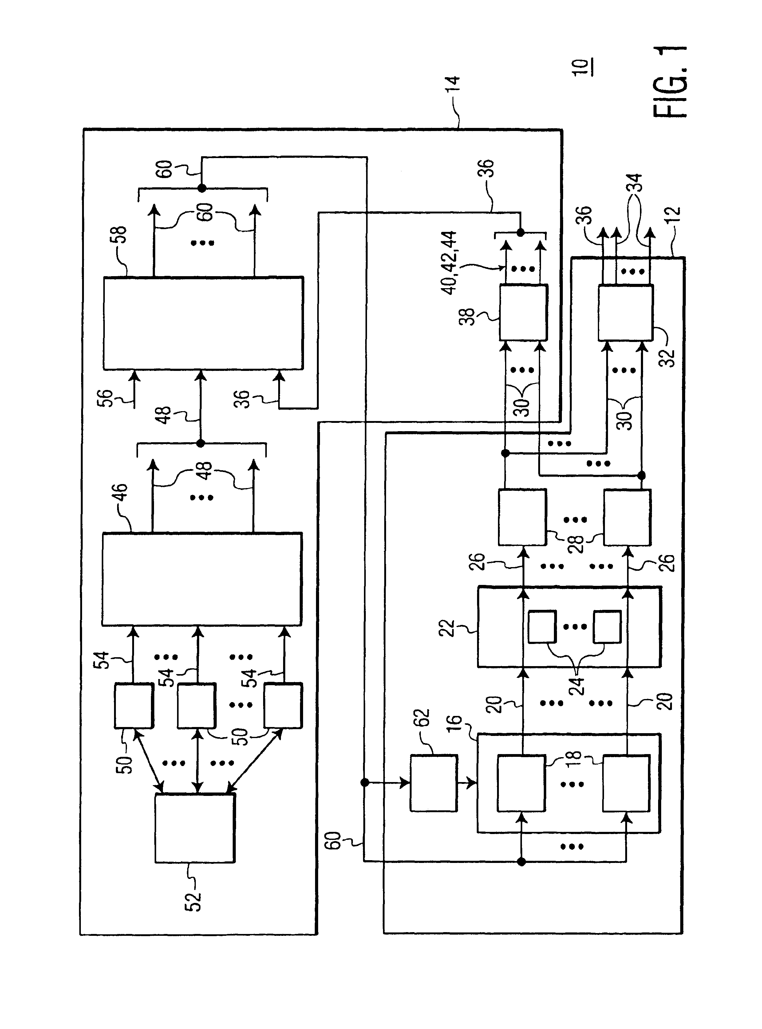
Referring to FIG. 1, therein is shown a diagrammatic representation of a Device 10 using one or more signals transmitted through or reflected from tissue or an organ to measure or monitor a parameter of the tissue or the organ and in which the present invention may be implemented. As discussed herein above, an example of such a Device 10 may be a blood oximetry device, and a Device 10 may be a self contained device or may be a part of a larger system that may include a plurality of Devices 10 of different types.

As illustrated in FIG. 1, a Device 10 will include a Parameter Measurement Unit 12 for making measurements of one or more parameters of the tissue or organ, typically and in the present invention by measuring light transmitted through or reflected from the tissue or organ. According to the present invention, a Emitted Signal Power Control Unit 14 is associated with the Parameter Measurement Unit 12, either as a part of the Device 10 or as a separate but associated unit, and ...


PUM


Abstract

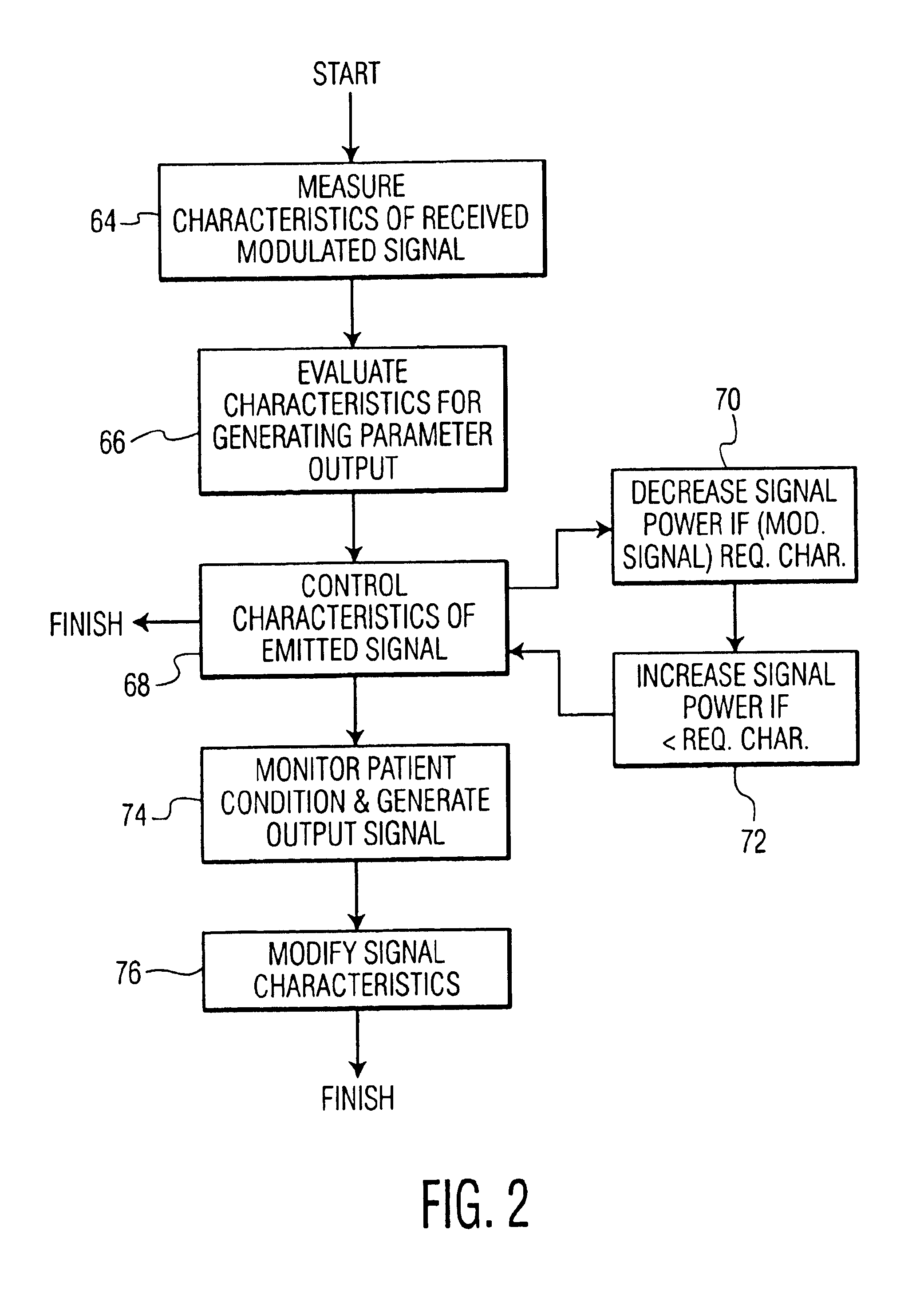
A system and method for adjusting power employed by a light emitting device used for medical applications, such as measurement of patient parameter. A system or device includes a light emitting device, a power unit coupled to the light emitting device for powering the light emitting device and responsive to a control signal for adjusting power applied to the light emitting device, and a control unit for providing the control signal and coupled to the power unit, the control signal being determined in response to a characteristic of a signal associated with a physiological parameter measured using light produced by the light emitting device.

Description

FIELD OF THE INVENTIONThe present invention relates to a method and apparatus for controlling and reducing the level of power consumption in medical devices and, in particular, for controlling and reducing the level of power consumption in medical devices, such as blood oximetry devices, employing transmitted or reflected signals or both in combination to measure biological or environmental parameters of a patient or to communicate information pertaining thereto.BACKGROUND OF THE INVENTIONThe medical field commonly employs a wide range of devices that depend upon the transmission of signals to monitor or measure various biological or environmental parameters of a patient. The signals may be transmitted and measurements made of the signal as reflected from or transmitted through, for example, tissue or an organ, or the signal may be used to communicate measured data rather than to obtain the data.For example, a common example of devices that employ the transmission and reception of s...

Claims


Application Information

Patent Timeline
IPC IPC(8): A61B5/00A61B5/0245A61B5/145A61B5/1455
CPCA61B5/14551A61B5/7221A61B2560/0209
Inventor HUANG, JOHNNIE W.MOZUR, MATTHEWKELLY, CLIFFORD MARKRILEY, MICHAEL JOSEPHBERNSTEIN, MICHAEL J.
Owner DRAGERWERK AG
Learn More