
Pintle hitch protective lock assembly

a pintle hitch and lock technology, applied in the direction of bolts, threaded fasteners, lock applications, etc., can solve the problems of equipment and trailers being subject to theft, chains and locks used to secure them being subject to tampering, and not being able to leave or store such trailers or trailer mounted equipment in secured areas, etc., to achieve the effect of low cos

Inactive Publication Date: 2005-03-08
HUBBART JAMES R
View PDF11 Cites 16 Cited by
  • Summary
  • Abstract
  • Description
  • Claims
  • Application Information

AI Technical Summary

Benefits of technology

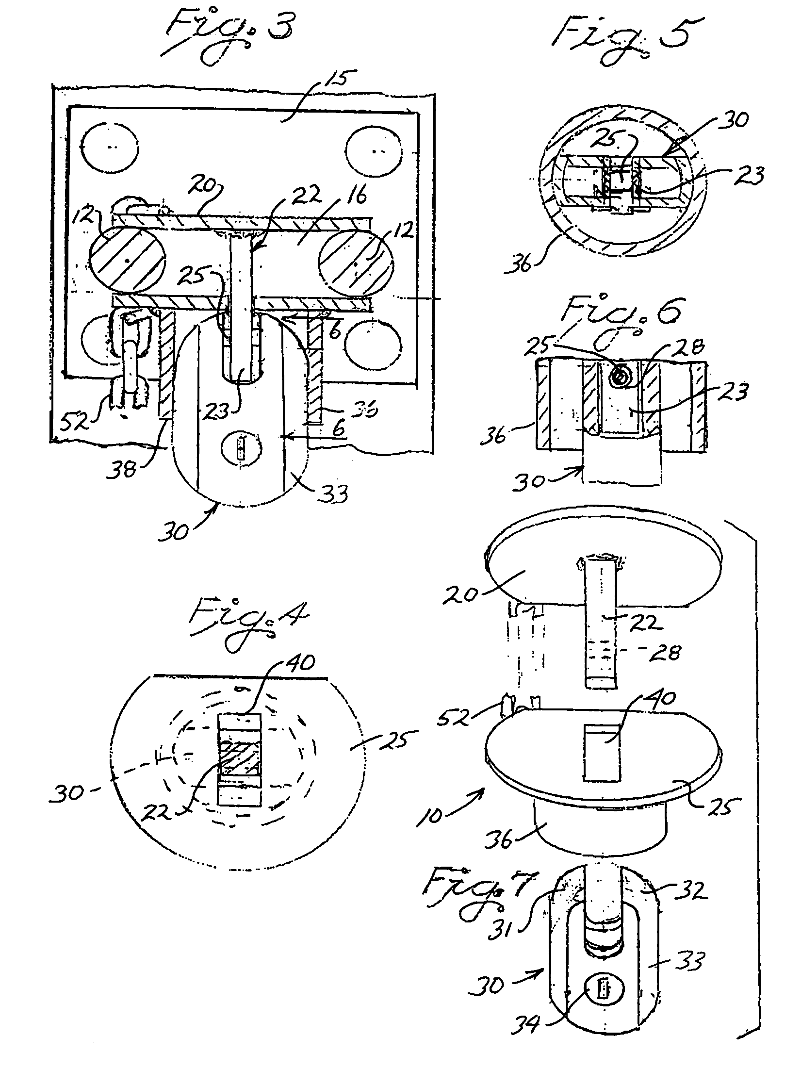
The housing is of a sufficient length such that when the two plates are mounted to the hitch that the tongue of the one plate remains encircled by the housing. The tongue further includes structure for cooperatively receiving a shackle or bolt of a conventional lock which is inserted within the housing and thereafter closed into engagement with the tongue to thereby prevent the separation of the two plates relative to the hitch. Further, the structure of the housing fully surrounds and thereby conceals the shackle or lock bolt associated with the conventional lock thus preventing access thereto when the plates are locked into assembled relationship.
In accordance with a further embodiment of the invention, to facilitate handling of the protective device of the present invention, the two plate components are preferably flexibly jointed such as by a length of chain or cable to thereby prevent the accidental displacement of the two components but also permitting the components to be maneuvered so as to be brought into a locked relationship with a hitch as described above.
It is yet a further object of the present invention to provide a very secure, sturdy and low cost protective device for deterring theft of trailers and trailer mounted equipment wherein the device can be secured to the hitch of the trailer or trailer mounted equipment in such a manner that a lock used to secure the device in place can not be tampered with utilizing bolt cutters or other tools.

Problems solved by technology

It is often not possible to leave or store such trailers or trailer mounted equipment in secured areas.
Often, it is necessary that such equipment and trailers be left on site and, unfortunately, such equipment and trailers are subject to misappropriation or theft.
Unfortunately, such chains and the locks used to secure them are subject to tampering using bolt cutters and other devices.
However, in many such assemblies, the lock bolt or lock shackle may be easily accessed so that the shackle or bolt can be tampered with utilizing bolt cutters or other tools.

Method used


Image

  • Pintle hitch protective lock assembly
  • Pintle hitch protective lock assembly
  • Pintle hitch protective lock assembly

Examples


Embodiment Construction

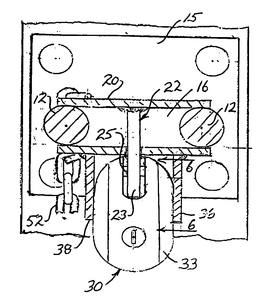
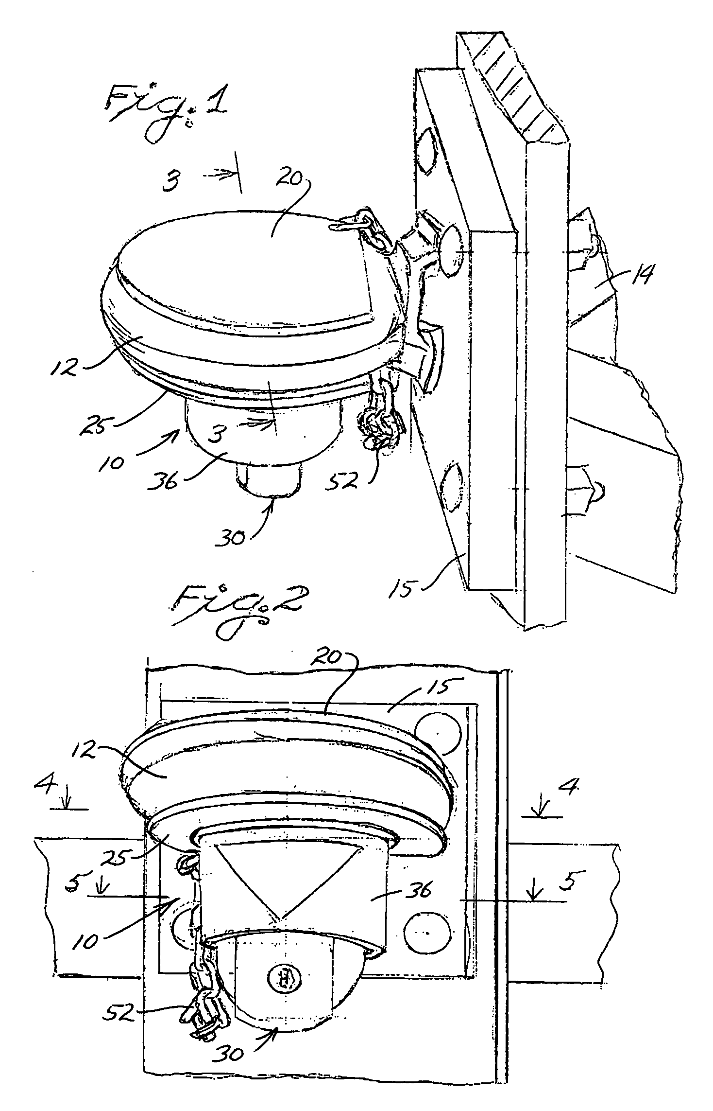
With continued reference to the drawing figures, the protective lock assembly 10 of the present invention is shown in FIG. 1 as being mounted within a hitch 12 of a trailer (not shown). The hitch is shown as being mounted to the front of the trailer tongue 14 on mounting plates 15. The hitch is in the form of a ring having an opening 16 therethrough, as shown in FIG. 3. The ring is of a size to receive a pintle associated with the hitch assembly of a towing vehicle (not shown).

The protective lock assembly 10 includes a first plate 20 of a size to be seated along either the upper or lower surface of the hitch ring as is shown in FIGS. 1-3. In the drawing figures, the plate 20 is shown as being seated on the upper surface of the hitch ring, however, the structure of the present invention also permits the plate 20 to engage the lower surface of the ring. Extending from the plate 20 is a post or tongue 22 which extends from the plate at a given distance as will be described in greater...


PUM


Abstract

A protective lock assembly for preventing unauthorized access to a pintle receiving hitch which assembly includes opposing plate members which are mounted on opposite surfaces of the hitch and wherein a tongue carried by one plate member is engageable by a lock whose shackle is protectively seated within a housing which extends from the other plate member.

Description

BACKGROUND OF THE INVENTION 1. Field of the Invention This invention is generally directed to devices for use in preventing unauthorized access to hitches of the type which are used to receive a pintle of a towing vehicle and which are often associated with heavy duty trailer type equipment used in construction and in maintenance. More particularly, the present invention is directed to a protective device which functions to seal off a hitch ring of a trailer device so that it can not be towed by unauthorized personnel and wherein the device is locked to the hitch ring in such a manner that unauthorized tampering of the lock, shackle or bolt is prevented. 2. Description of the Related Art Equipment used in the construction and maintenance industry is frequently mounted on a trailer to promote portability. Many such heavy duty type trailers utilizing a hitch which is adapted to be mounted to a tongue of a towing vehicle by way of a pintle which extends through an opening in a circula...

Claims


Application Information

Patent Timeline
Patent Type & Authority Patents(United States)
IPC IPC(8): E05B73/00B60D1/60
CPCB60D1/60Y10T70/40Y10T70/498Y10T70/5867Y10T70/5982
Inventor HUBBART, JAMES R.
Owner HUBBART JAMES R
Learn More