
Firearm breech safety lock

Inactive Publication Date: 2005-03-08
CANADAY BENJAMIN +2
View PDF43 Cites 23 Cited by
  • Summary
  • Abstract
  • Description
  • Claims
  • Application Information

AI Technical Summary

Benefits of technology

A principal object of the present invention is to provide an improved safety device by having means on the dummy cartridge that resists rotation of the dummy device in the chamber when turning the threaded rod during installing or uninstalling the device.
A still further object is to provide a firearm safety device with a simple one piece dummy cartridge that has a threaded bore extending therein from one end thereof.
A still further object is to provide a firearm safety device with a simple one piece dummy cartridge with a threaded bore in one end thereof and an enlarged entry gradually decreasing in size in direction toward the threaded portion and thereby providing means to direct and guide the end of the elongate threaded rod toward the threads.

Problems solved by technology

Nothing is provided by the patentee that prevents the dummy cartridge from rotating in the chamber when the hand tool is used to un-thread the rod and in some instances this can make the task difficult and perhaps even impossible.
The construction is complicated and therefore relatively expensive to produce as compared to the instant invention.
Furthermore no means is provided to protect the gun chamber from the insert and damage thereto that possibly can occur through repeated use of the same.

Method used


Image

  • Firearm breech safety lock
  • Firearm breech safety lock
  • Firearm breech safety lock

Examples


Embodiment Construction

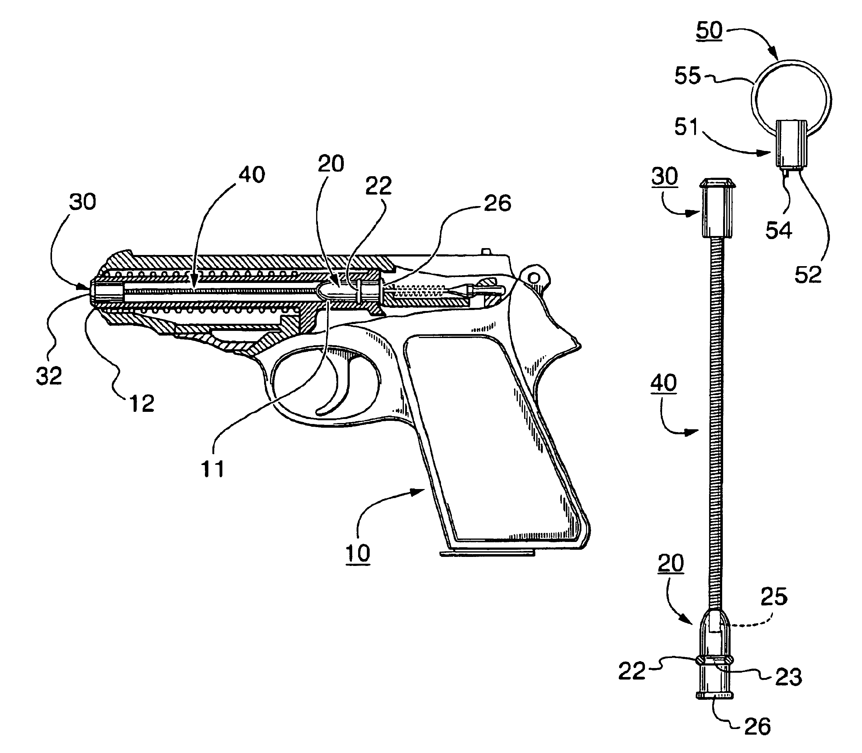
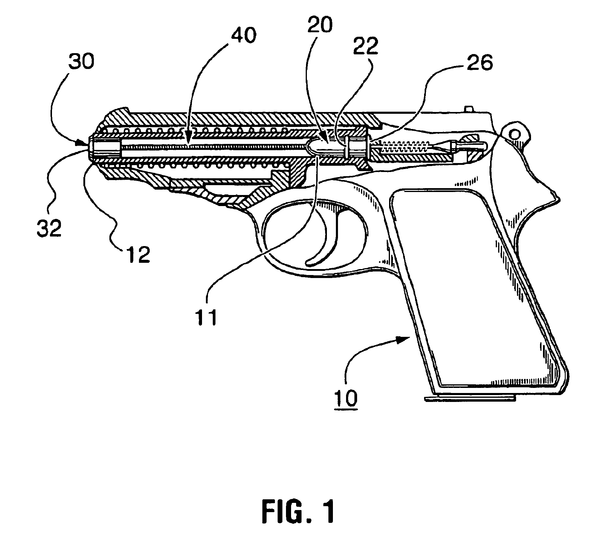
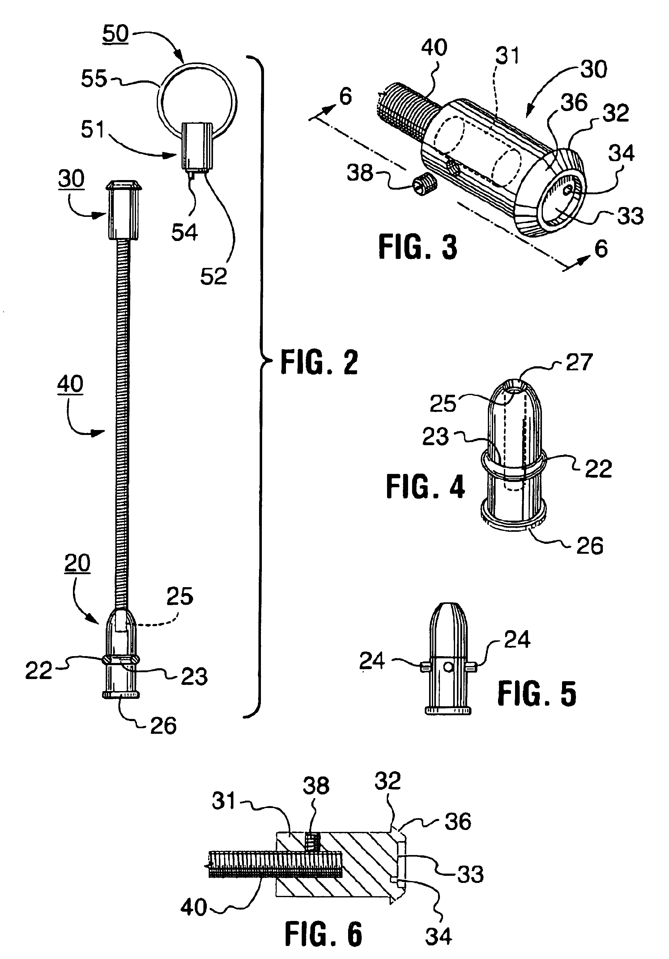
Referring to the drawings, FIG. 1 illustrates a partial side sectional view of a hand gun 10 having a safety device of the present invention installed therein to prevent unauthorized use or accidental discharge of the gun. The safety device consists of a dummy cartridge 20, a muzzle end plug 30, and an elongate threaded rod 40 inter-connecting the two. A key 5 as best shown in FIG. 2 is provided for installing and un-installing the device.

The dummy cartridge is a solid body of metal such as aluminum steel, copper, or preferably brass, or other suitable material such as nylon, fiber glass, wood, rubber, TEFLON, carbon composite material, polymeric material, or even paper composite. The dummy cartridge is shaped to generally conform with that of a live cartridge designed to be used with the particular firearm at hand, or which duplicates the size, shape and dimensions of a live cartridge commercially available. Of course, the dummy cartridge differs from the live cartridge in that the...


PUM


Abstract

A safety device for preventing unauthorized or accidental use of a gun. The safety device includes a solid body of material, a muzzle end plug and an elongate threaded rod inter-connecting the same. The solid body is sized and shaped to simulate a live cartridge. It has an outwardly directed flange at one end for engaging an end wall surrounding entry into the cartridge chamber of the gun and a threaded bore extending inwardly a selected distance from the opposite end. An O-ring fits into a groove it the solid body and projects outwardly frictionally to engage the inner wall surface-of the gun barrel in the cartridge chamber. The muzzle plug has an outwardly directed flange at one end thereof that engages an outer end of the gun barrel. The muzzle plug has a recess in the outer end face remote from the elongate rod and in a preferred embodiment beyond the recess there is chamfered surface tapering to the extent that the outwardly directed flange has a thin narrow edge that cannot be gripped by pliers or the like. A key has a projection that mates with the recess in the muzzle plug. A pin projects from the key projection and fits into a small recess in the base of the first mentioned plug recess.

Description

BACKGROUND OF THE INVENTIONTechnical FieldThe present invention relates generally to a firearm breech safety device to prevent unauthorized or accidental discharge of he firearm.BACKGROUND OF THE INVENTIONFirearm safety devices are known and by way of example reference maybe had to U.S. Pat. No. 4,224,753 granted Sep. 30, 1980 to T. F. Bielman. This patent is closely related to the present invention and is the most pertinent reference known to the applicant. The substance of the foregoing patent is incorporated herein by reference thereto.The Bielman patent teaches a safety device which includes a dummy cartridge that fits into the chamber of the barrel and is connected to a barrel end plug or muzzle cap by a threaded elongate rod. A hand tool is used to un-thread the rod from the dummy cartridge permitting removal of the muzzle cap and rod. Nothing is provided by the patentee that prevents the dummy cartridge from rotating in the chamber when the hand tool is used to un-thread the ...

Claims


Application Information

Patent Timeline
IPC IPC(8): F41A17/44F41A17/00
CPCF41A17/44
Inventor CANADAY, BENJAMIN J.
Owner CANADAY BENJAMIN
Learn More