
Channel tube coupling structure for anti-pollution type endoscope

a technology of anti-pollution endoscope and coupling structure, which is applied in the field of anti-pollution endoscope coupling structure of channel tube coupling structure, can solve the problems of troublesome procedure for coupling and separation of tubes, and achieve the effect of easy and smooth coupling

Inactive Publication Date: 2005-03-01
HOYA CORP
View PDF15 Cites 80 Cited by
  • Summary
  • Abstract
  • Description
  • Claims
  • Application Information

AI Technical Summary

Benefits of technology

is to provide a channel tube coupling structure for an anti-pollution type endoscope which can easily and smoothly couple a multi-lumen type ch

Problems solved by technology

However, when such a multi-lumen tube is employed as the channel tube, the coupling direction and the operation number of time for coupling with and separating from the tubes on the endoscope (for example, the air supply tube, the water supply tube, the suction tube) become plural, so that the procedures for the coupling and separation of the tubes becomes troublesome.

Method used


Image

  • Channel tube coupling structure for anti-pollution type endoscope
  • Channel tube coupling structure for anti-pollution type endoscope
  • Channel tube coupling structure for anti-pollution type endoscope

Examples


Embodiment Construction

The embodiments of the invention will be explained with reference to the accompanying drawings.

FIGS. 6 and 7 show the entire configuration of the system of an anti-pollution type endoscope. FIG. 6 shows a state where an insertion portion 11 of an endoscope 10 is not covered by an outer sheath 30. FIG. 7 shows a state where the insertion portion 11 of the endoscope 10 is covered by the outer sheath 30.

The insertion portion 11 of the endoscope 10 is configured in a flexible tubular shape. An observation window 12 and a not-shown illumination window etc. are disposed at the tip end of the insertion portion 11. An operation portion 13 is coupled to the base end of the insertion portion 11.

A transparent tip end cap 31 is attached to the tip end portion of the outer sheath 30 which is detachably attached to the insertion portion 11 to cover the insertion portion 11. A suction port 33 and an air / water supply nozzle port 34 are opened at the surface of the tip end cap 31.

A channel tube 32 i...


PUM


Abstract

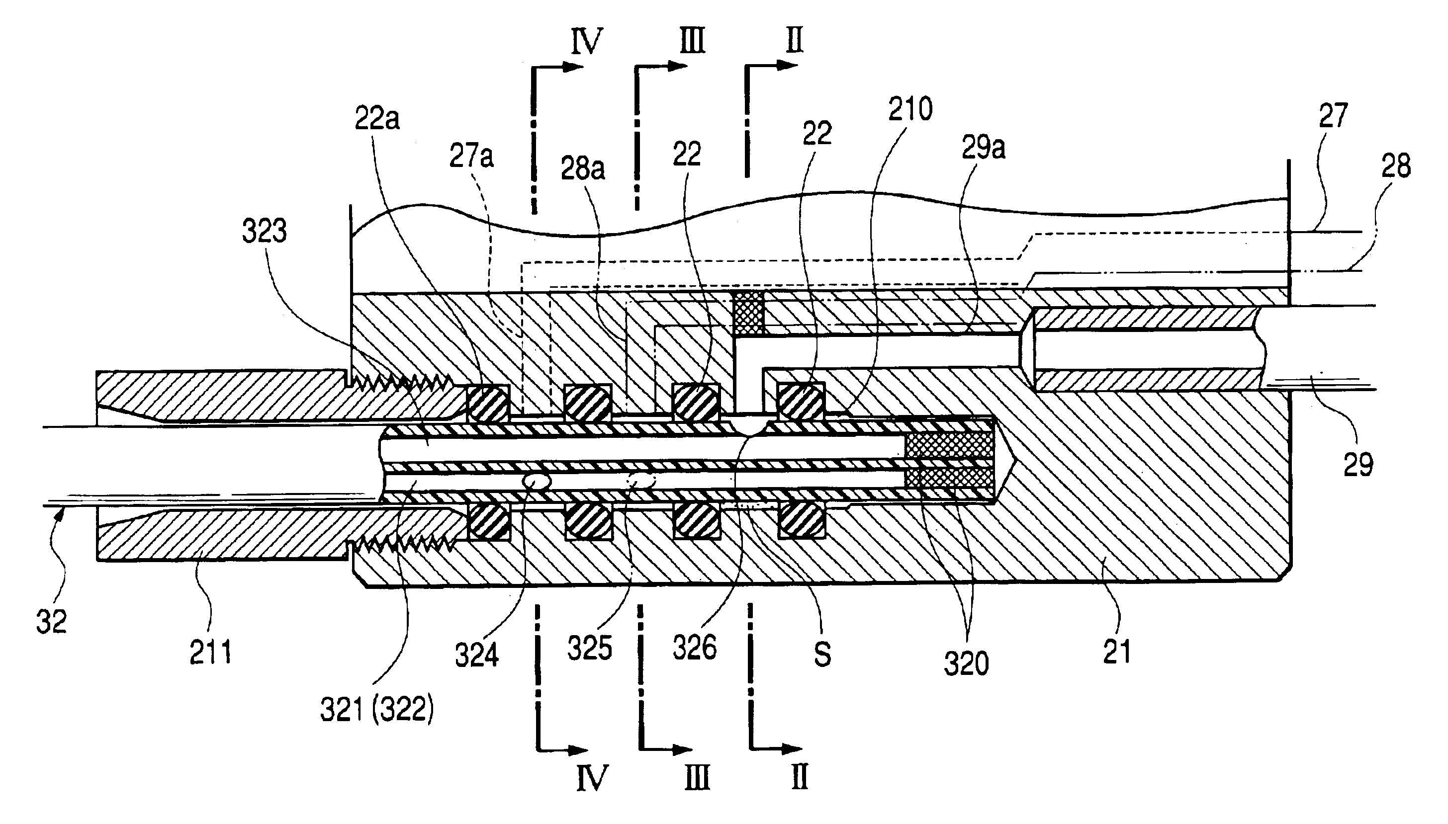
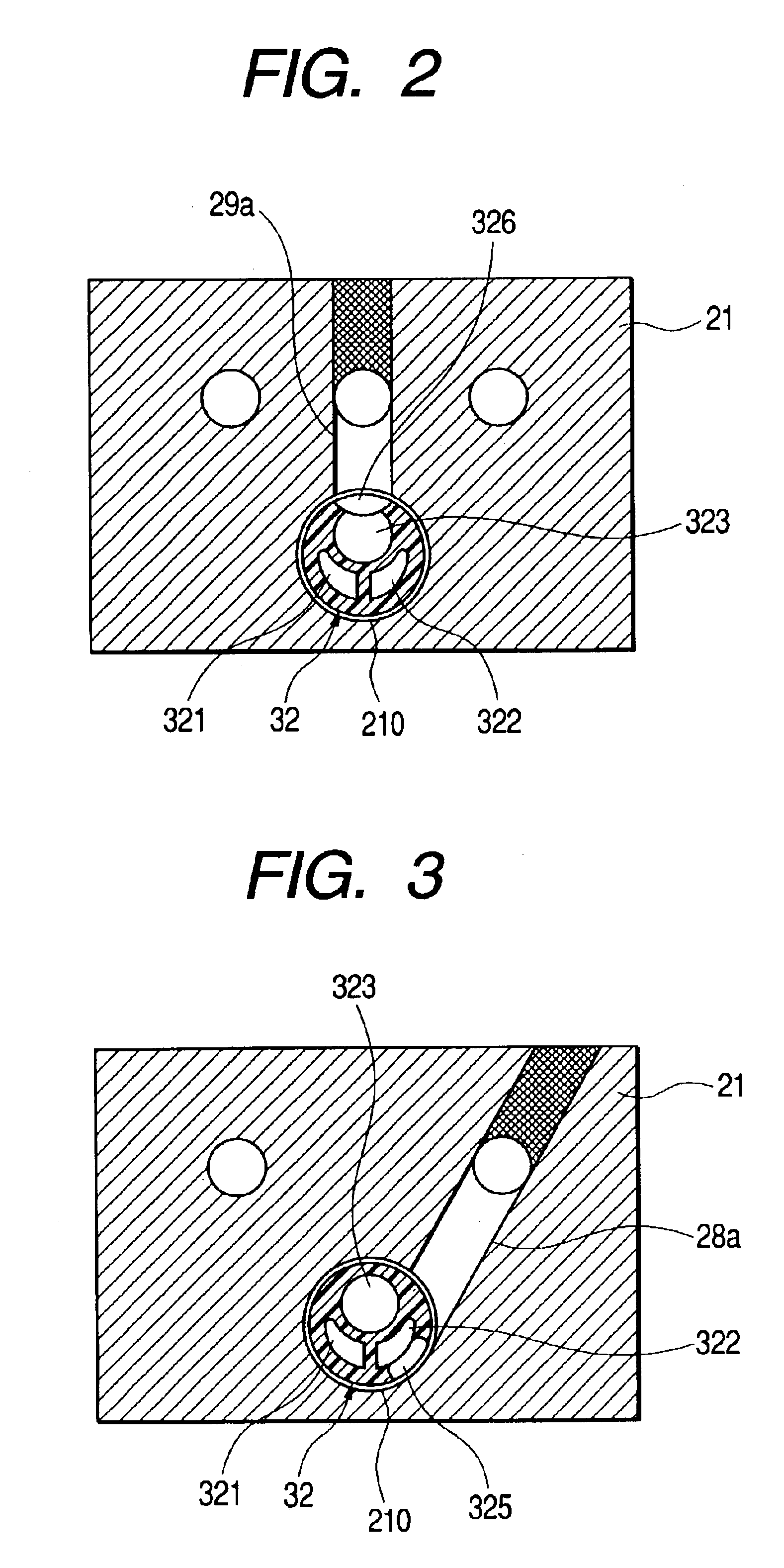
A channel tube coupling structure for an anti-pollution type endoscope which can easily and smoothly couple a multi-lumen type channel tube extending from a base end of an outer sheath with tubes on a side of the endoscope and separate the multi-lumen type channel tube therefrom. At a side surface in a vicinity of the base end of the channel tube, side holes communicate with a plurality of tubes that are formed so as to be shifted from one another in an axial direction. A coupling hole, where the base end portion of the channel tube is loosely inserted thereinto and freely removed therefrom, provides a space in a radial direction between the channel tube and the coupling hole. Annular sealing members are provided which seal portions between the respective side holes, in a state where the base end portion of the channel tube is inserted into the coupling hole. Respective holes on the endoscope side are opened and coupled at the inner peripheral surface of the coupling hole at portions along the annular sealing members.

Description

BACKGROUND OF THE INVENTIONThe present invention relates to a channel tube coupling structure for an anti-pollution type endoscope having an insertion portion to which an outer sheath is detachably attached.In order to prevent the insertion portion of the endoscope to be inserted within a human body from being polluted by polluted liquid within the human body, it is necessary not only to cover the insertion portion of the endoscope by an outer sheath but also to provide, in the outer sheath, a channel tube communicating with the interior of the human body so that fluid, a treatment instrument etc. can pass through the channel tube.Such a channel tube is inserted into and disposed within the outer sheath which is arranged to cover the insertion portion of the endoscope so as to be detachable freely. Further, the channel tube is configured in a manner that the base end portion thereof extending from the base end of the outer sheath is freely coupled with and separated from tubes on th...

Claims


Application Information

Patent Timeline
IPC IPC(8): F16L39/04F16L39/00
CPCA61B1/00142A61B1/00128F16L39/04
Inventor OUCHI, TERUOYAMAMOTO, KAZUYUKI
Owner HOYA CORP
Learn More