
Device and method for detecting oil deterioration

a technology for automotive vehicles and oil deterioration, which is applied in the direction of instruments, transportation and packaging, material impedance, etc., can solve the problems of not being able to detect not being able to judge the degree of deterioration of oil,

Inactive Publication Date: 2005-02-22
DENSO CORP
View PDF7 Cites 92 Cited by
  • Summary
  • Abstract
  • Description
  • Claims
  • Application Information

AI Technical Summary

Benefits of technology

Accordingly, an object of the present invention is to provide an oil deterioration detection method and device capable of detecting an end point of the service life and the behavior in the vicinity of the end point of the service life of a vehicle oil more accurately, and a method and a device for warning the vehicle user of the detected oil deterioration.
This method enables the warned vehicle user to take appropriate protective measures in response to the warning, for example, by exchanging old oil with new oil.

Problems solved by technology

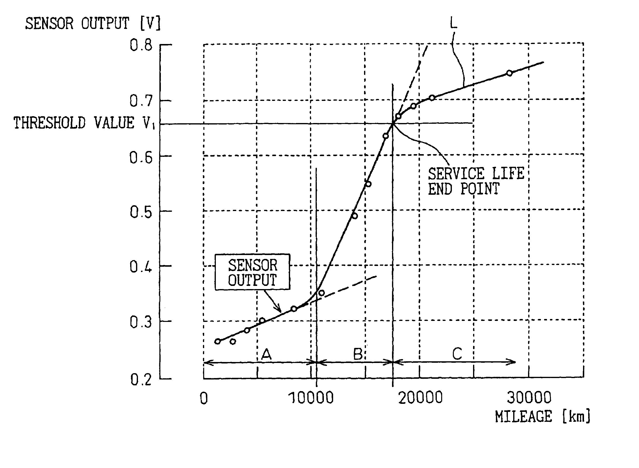
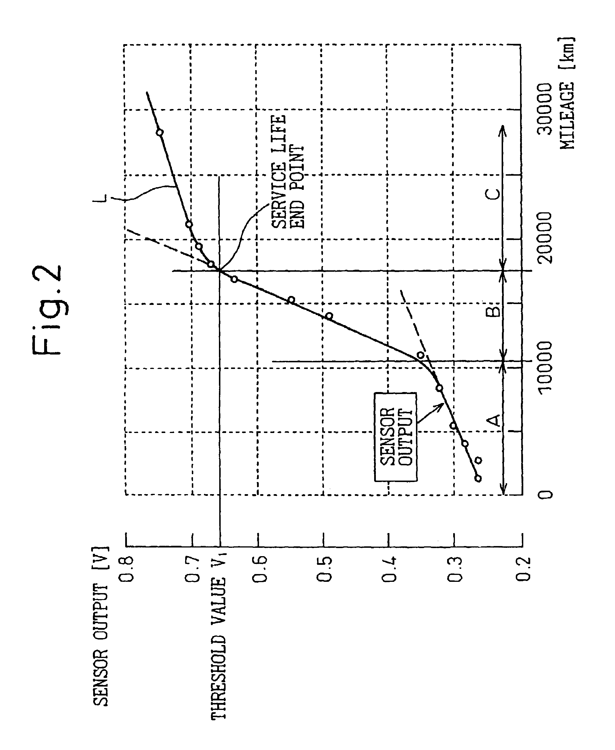
However, there has been no conventional method or apparatus for detecting the oil deterioration which is capable of detecting the end point of the service life of the oil or the progress of the oil condition in the vicinity of the end point of the service life more accurately, without any influence of output characteristics of the sensors, by monitoring the output characteristic of the pH sensor with respect to the mileage covered by the vehicle to perceive the behavior of the additives in the oil.
However, this device does not judge the degree of deterioration by monitoring a change rate of the output from the pH sensor for the driving mileage or driving time.
However, the device does not judge the deterioration of the oil by detecting a change in the sensor output from a condition of a large change rate into a condition of a small change rate.

Method used


Image

  • Device and method for detecting oil deterioration
  • Device and method for detecting oil deterioration
  • Device and method for detecting oil deterioration

Examples


second embodiment

the present invention will be also described below with reference to the drawings. The change in the change rate of the output from the pH sensor 11 is detected, in the first embodiment, based on the change in the inclination of the approximation line of the output from the pH sensor. On the other hand, it is detected, in this second embodiment, based on a change in an inclination of a vector (i.e., an angle formed between a sense of the vector and a positive direction of the lateral axis) in a line plot of the output from pH sensor 11 with respect to a total driving mileage or time. This is the reason why, in the case of using an approximation line, as this approximation line is calculated based on a series of data obtained at regular intervals, all of these data must be stored in memory in order to obtain an exact approximation line, resulting in a requirement for a high-capacity memory and consequently in an increased cost. In the above description, the term “the change rate of t...


PUM

PropertyMeasurementUnit
acidityaaaaaaaaaa
basicityaaaaaaaaaa
thresholdaaaaaaaaaa

Abstract

A method and a device for detecting a deterioration of vehicle oil are disclosed in which the end point of the oil service life can be detected with higher accuracy, while at the same time detecting the progress of the oil condition in the vicinity of the end point of the oil service life. The acidity or basicity of the vehicle oil is measured using a pH sensor (11) generating an output in responding to the degree of the acidity or basicity. The deterioration of the vehicle oil can be detected based on the fact that with the increase in vehicle mileage, a line approximating the output of the pH sensor (11) with respect to the vehicle mileage has a tendency to change from a first inclination to a second inclination larger than the first inclination and then from the second inclination to a third inclination smaller than the second inclination.

Description

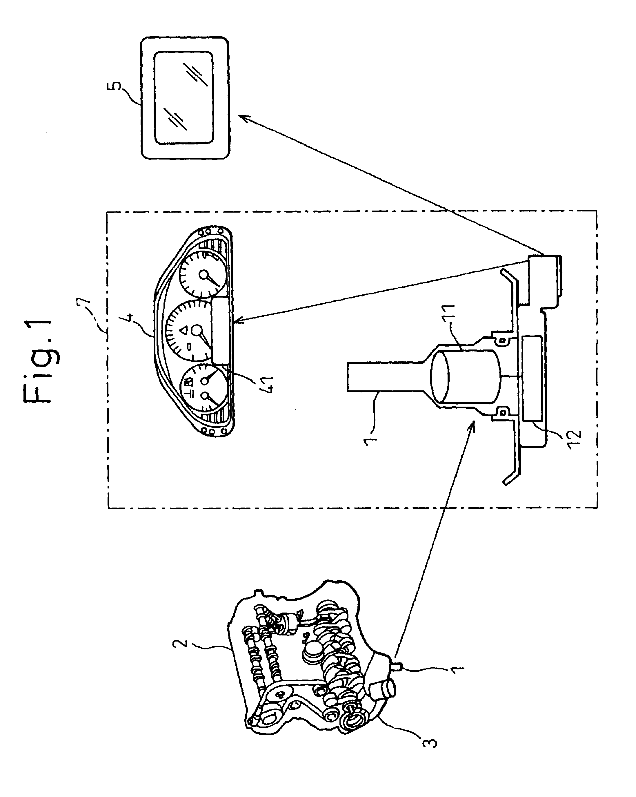
BACKGROUND OF THE INVENTION1. Field of the InventionThe present invention relates to a method and a device for detecting deterioration of automotive vehicle oil, such as engine oil, using a pH sensor which generates an output in response to the degree of the acidity or basicity of the oil, and a method and a device for warning a vehicle user of detected oil deterioration.2. Description of the Related ArtA conventional pH sensor has been known for detecting the acidity or basicity of an aqueous solution directly and continuously using electrodes. This conventional pH sensor includes a reference electrode presenting a constant electrode potential, and a pH electrode presenting an electrode potential changing in response to the acidity or basicity of the aqueous solution. The pair of electrodes, when immersed in an aqueous solution to be measured, develop a potential difference, substantially proportional to the degree of the acidity or basicity, between them. By measuring this potenti...

Claims


Application Information

Patent Timeline
Patent Type & Authority Patents(United States)
IPC IPC(8): G01N33/28G01N33/26
CPCG01N33/2888
Inventor HORIE, KAZUYUKINAITO, KIWAMU
Owner DENSO CORP
Learn More