
Remote cable assist

a remote cable and assist technology, applied in the direction of alarms, signalling systems, instruments, etc., can solve the problems of user difficulty in connecting the communication cable to the proper receptacle, the foregoing connection difficulty is generally worse, and the location of the proper receptacle for the communication cable may be uncertain or difficult to identify

Inactive Publication Date: 2005-02-22
VALTRUS INNOVATIONS LTD +1
View PDF8 Cites 106 Cited by
  • Summary
  • Abstract
  • Description
  • Claims
  • Application Information

AI Technical Summary

Problems solved by technology

In certain applications, the location of the proper receptacle for the communication cable may be uncertain or difficult to identify.
For example, a user may have difficulty connecting the communication cable to the proper receptacle if it is located in a dark area, a tight space, or another area having limited accessibility or visibility.
The foregoing connection difficulties are generally worse in applications having multiple receptacles for communication cables.
Accordingly, a user may be unable to locate the appropriate port for the desired communication cable.

Method used


Image

  • Remote cable assist
  • Remote cable assist
  • Remote cable assist

Examples


Embodiment Construction

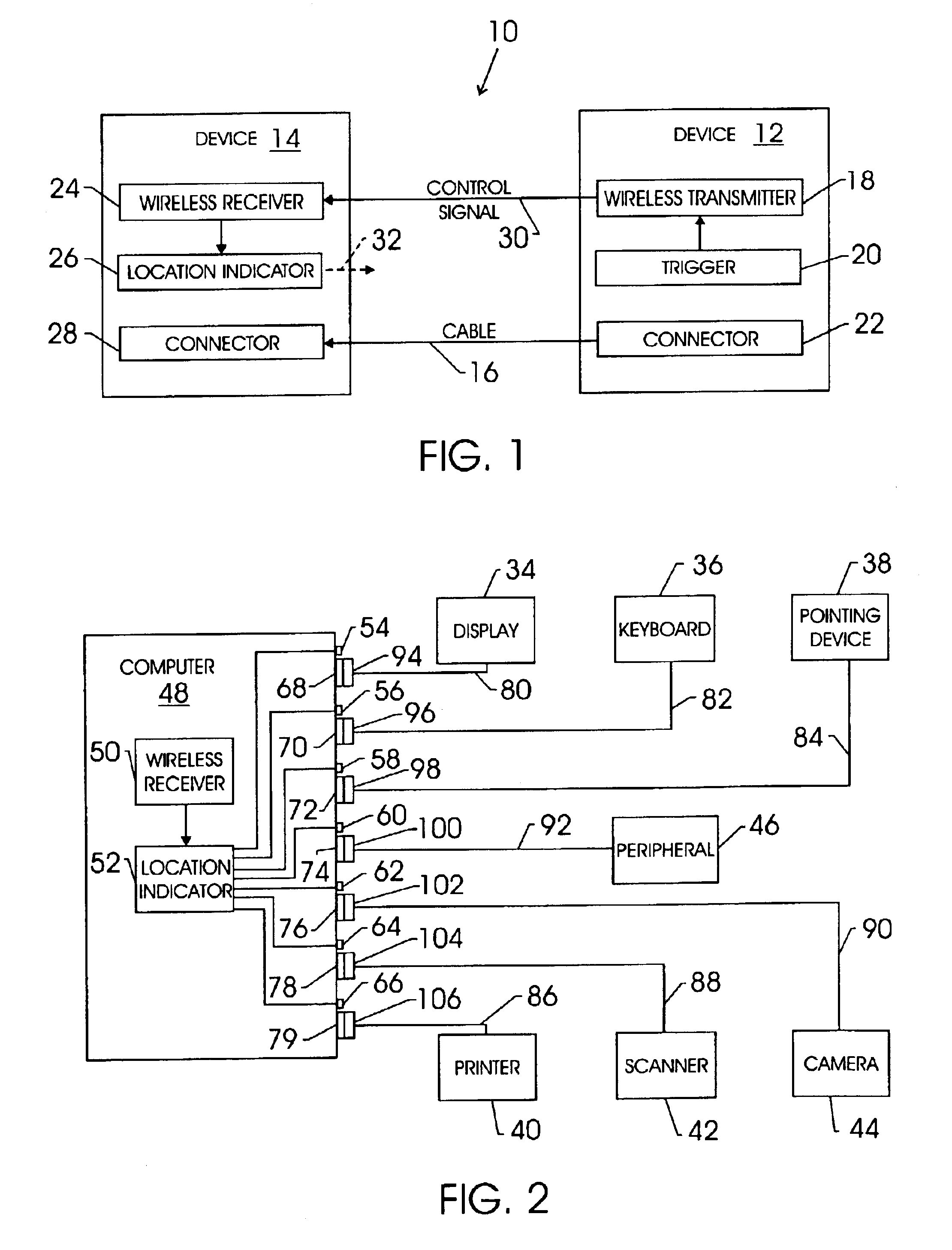
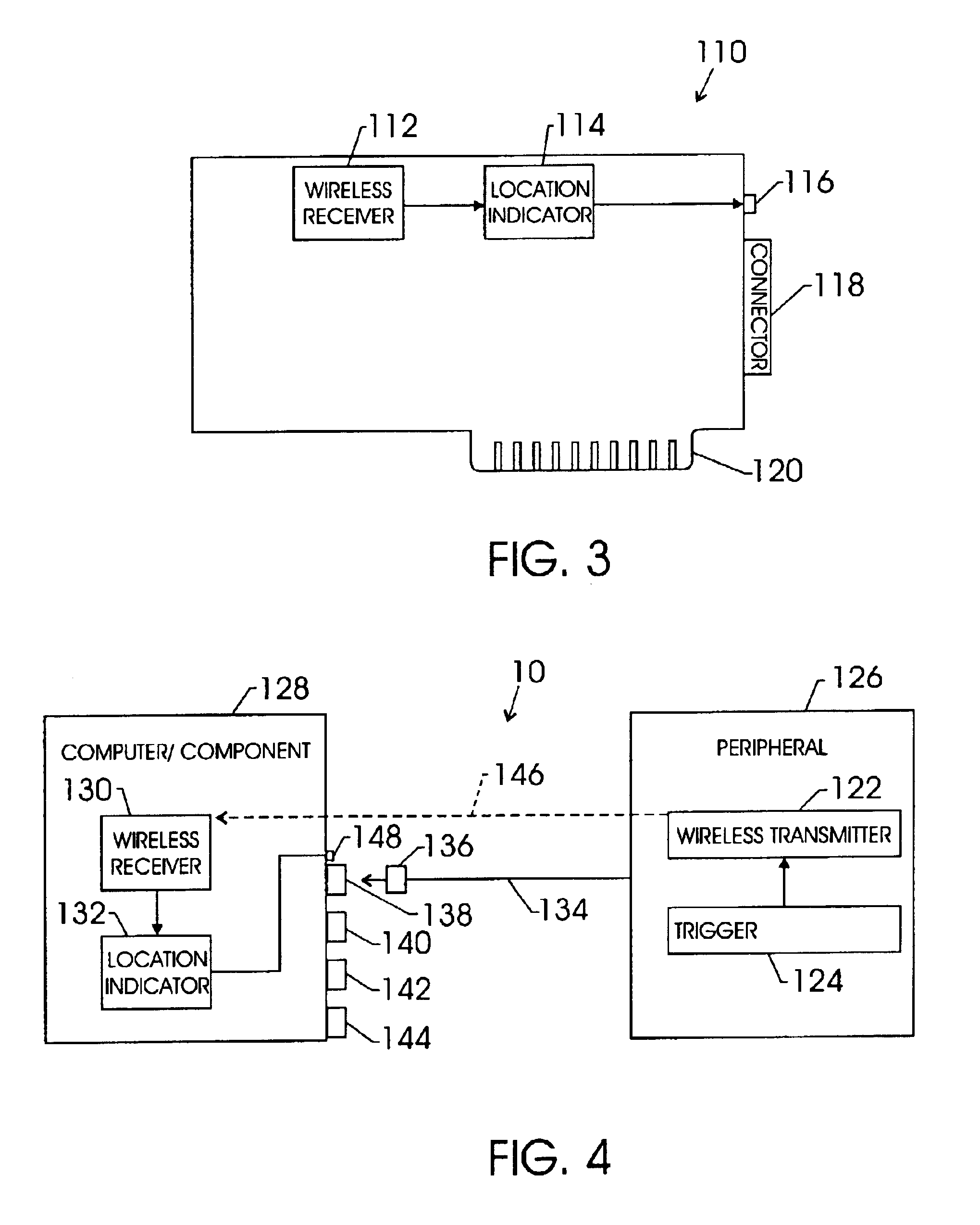
FIG. 1 is a block diagram of a system 10 in accordance with certain embodiments of the present invention. As illustrated, the system 10 comprises devices 12 and 14 communicatively coupled together via a cable 16. As discussed in further detail below, the devices 12 and 14 may comprise a wide variety of electronics, computer components and peripherals, network devices, and so forth. For example, the devices 12 and 14 may comprise electronic devices disposed in separate locations, such as in a network. Accordingly, the system 10 may comprise a computer system, a network, or any other connectable system of devices.

As illustrated, the device 12 comprises a wireless transmitter 18, a trigger 20, and a connector 22, while the device 14 comprises a wireless receiver 24, a location indicator 26, and a connector 28. The wireless transmitter 18 and the wireless receiver 24 may comprise radio frequency (RF) circuitry, infrared or other optical communication circuitry, blue tooth technology, or...


PUM


Abstract

A communication cable comprising a trigger and a wireless transmitter coupled to the trigger and adapted to transmit a wireless transmitter coupled to the trigger and adapted to transmit a wireless signal to activate a user identifiable locator adjacent a cable connector disposed on a device. A processor-based system a cable connector, a user identifiable locator disposed adjacent the cable connector, and a controller coupled to the user identifiable locator and triggerable wirelessly to facilitate guided connection between the cable connector and a communication cable.

Description

BACKGROUND OF THE INVENTIONElectronic devices, such as computer components and peripherals, are often coupled together via a communication cable. For example, a printer may be coupled to a laptop or desktop computer via a parallel cable. In certain applications, the location of the proper receptacle for the communication cable may be uncertain or difficult to identify. For example, a user may have difficulty connecting the communication cable to the proper receptacle if it is located in a dark area, a tight space, or another area having limited accessibility or visibility. The foregoing connection difficulties are generally worse in applications having multiple receptacles for communication cables. For example, a computer system may have one or more parallel ports, serial ports, Universal Serial Bus (USB) ports, Institute of Electrical and Electronics Engineers (IEEE)—1394 ports, network ports, modem ports, and so forth. Accordingly, a user may be unable to locate the appropriate po...

Claims


Application Information

Patent Timeline
Patent Type & Authority Patents(United States)
IPC IPC(8): G06F1/18G06F3/033G06F3/023H01R13/64G06F3/038
CPCG06F1/181G06F3/023G06F3/0383H01R2201/04H01R13/64
Inventor CONN, KEVIN D.
Owner VALTRUS INNOVATIONS LTD
Learn More