
Locking pliers

a technology of locking pliers and pliers, which is applied in the field of pair of locking pliers, can solve problems such as trouble for users in operation

Inactive Publication Date: 2005-02-22
WANG PANG CHUNG
View PDF2 Cites 21 Cited by
  • Summary
  • Abstract
  • Description
  • Claims
  • Application Information

AI Technical Summary

Problems solved by technology

Moreover, the user's hand might slide on the handles 8 and 3 that are made of metal, thus causing troubles for the user in operation.

Method used


Image

  • Locking pliers
  • Locking pliers
  • Locking pliers

Examples


Embodiment Construction

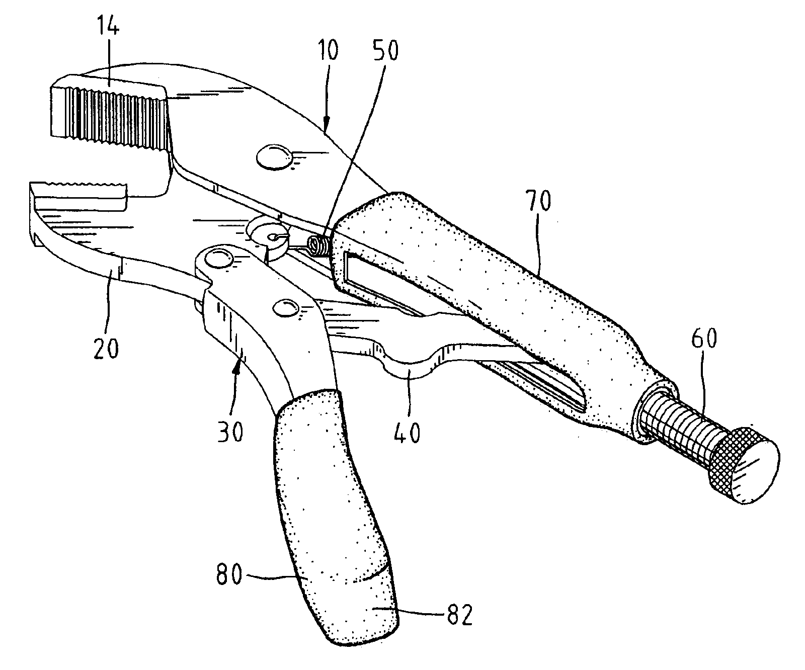
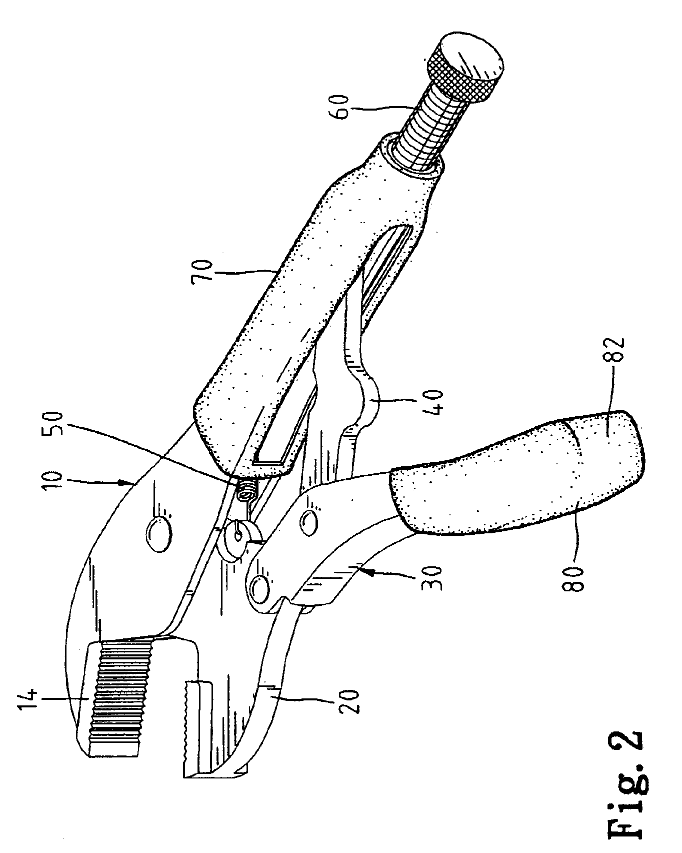
Referring to FIGS. 2 and 3, according to the preferred embodiment of the present invention, a pair of locking pliers includes a first jaw 14, a first handle 16, a second jaw 20, a second handle 30, a toggle 40, an adjusting screw 60, a release lever 31, a spring 50, a first soft anti-slip jacket 70, and a second soft anti-slip jacket 80.

The first handle 16 extends from the first jaw 14. Preferably, they are merged into one piece 10. The first handle 16 is hollow, i.e., defining a space 12 for receiving the spring 50 and the toggle 40. A hole 11 is defined in an end of the first handle 16 in order to receive the adjusting screw 60.

The second jaw 20 is pivotally connected with the first jaw 14 by a rivet (not numbered).

The second handle 30 is pivotally connected with the second jaw 20 by a rivet (not numbered).

A first end of the toggle 40 is pivotally connected with the second handle 30 by a rivet. A second end of the toggle 40 is inserted into the space 12 of the first handle 16.

The ...


PUM


Abstract

A pair of locking pliers includes a first jaw, a first handle, a second jaw, a second handle, a toggle, an adjusting screw, a release lever, a spring, and a soft jacket. The first handle extends from the first jaw and includes a space defined therein. The second jaw is pivotally connected with the first jaw. The second handle is pivotally connected with the second jaw. The toggle includes a first end pivotally connected with the second handle and a second end inserted into the space of the first handle. The adjusting screw includes an end driven into the space of the first handle for abutment against the second end of the toggle. The release lever is pivotally connected with the second handle. The release lever includes a first end for abutment against the toggle and a second end to be pressed by a user. The spring includes an end secured to the first handle and an opposite end secured to the second jaw. The soft jacket wraps up the second handle and the release lever.

Description

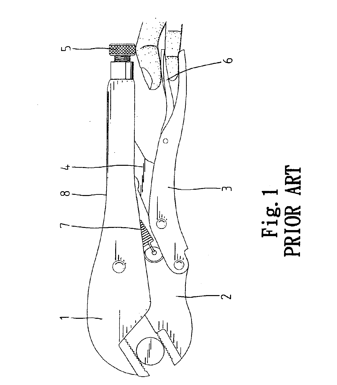
FIELD OF INVENTIONThe present invention relates to a pair of locking pliers.BACKGROUND OF INVENTIONReferring to FIG. 1, a pair of conventional locking pliers includes a first jaw 1, a first handle 8, a second jaw 2, a second handle 3, a toggle 4, an adjusting screw 5, a release lever 6 and a spring 7. The first handle 8 extends from the first jaw 1. The first handle 8 is hollow. The second jaw 2 is pivotally connected with the first jaw 1 by means of a rivet. The second handle 3 is pivotally connected with the second jaw 2 by means of a rivet. A first end of the toggle 4 is pivotally connected with the second handle 3 by means of a rivet. A second end of the toggle 4 is inserted into the first handle 8. The adjusting screw 5 is driven into the first handle 8. An end of the adjusting screw 5 abuts the second end of the toggle 4. An end of the spring 7 is secured to the second jaw 2. An opposite end of the spring 7 is secured to the first handle 8. Thus, the spring 7 tends to pull the...

Claims


Application Information

Patent Timeline
Patent Type & Authority Patents(United States)
IPC IPC(8): B25B7/12B25B7/00
CPCB25B7/123
Inventor WANG, CHAO-CHI
Owner WANG PANG CHUNG
Learn More