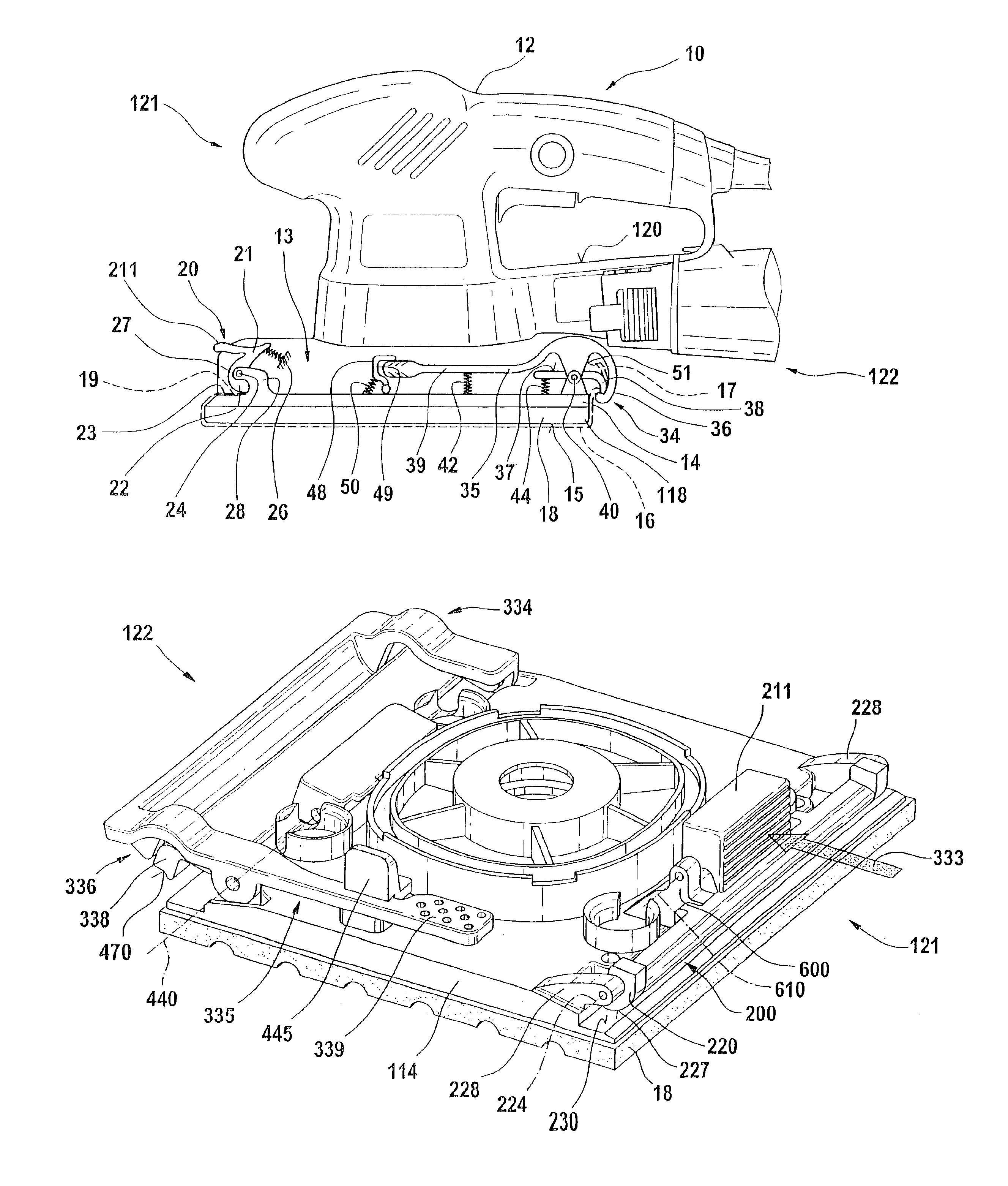
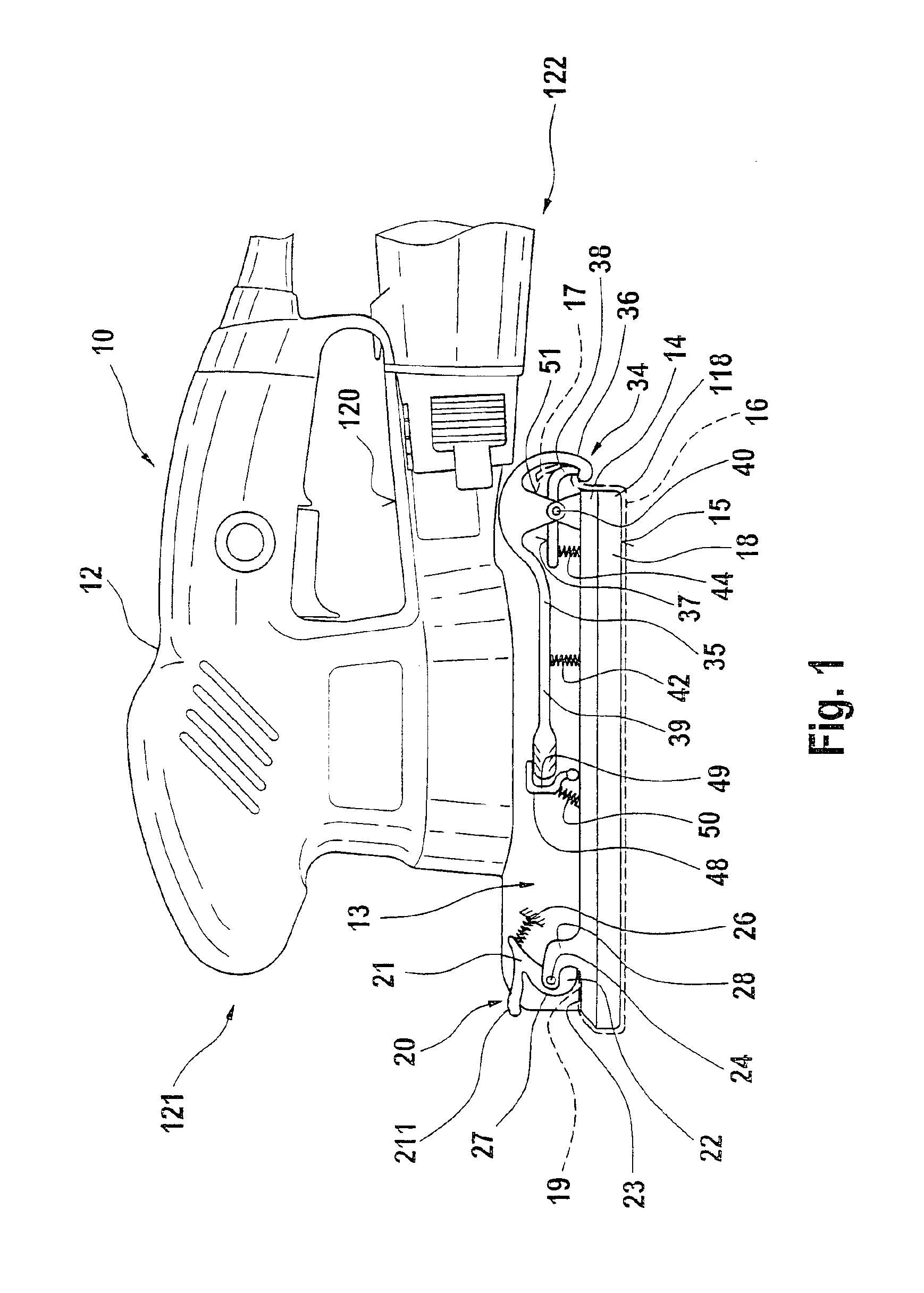
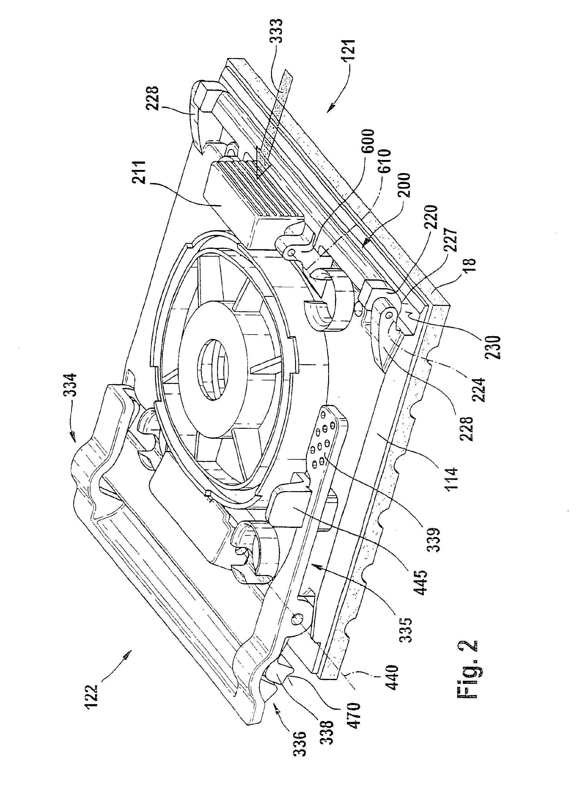
The pincer has the advantage that grinding sheets of any thickness can be fastened with maximal clamping force, since as a result of a long closing path, all dimensional differences can be sensitively compensated for, and a high clamping force that has previously never been achieved is attainable. Moreover, the power tool can be equipped with grinding sheets that—within limits—are of various lengths, because their protruding ends can be accommodated conveniently in the annularly designed active tensing jaw.
This is achieved by providing that the first grinding sheet end can be introduced—with only one hand—into a self-opening slot and clamped automatically there, and then the second grinding sheet end—again with only one hand—can be placed in the clamping-tensing device and is then tensable in taut fashion up to the tearing limit. The grinding sheet can thus be fixed firmly between the two clamping points and on the work face of the grinding holder so that in grinding, the relative motion between the grinding sheet holder and the grinding sheet is minimal. The result is greater abrasion performance and higher overall efficiency of the power grinder.
Because one of the clamping means is designed as a pincer, between which one grinding sheet end can be clamped, and the pincer together with the clamped grinding sheet end is movable about a pivot axis and can be arrested in an end position, convenient and secure clamping with subsequent taut tensing of the grinding sheet can be achieved by simple means.
The pincer has the advantage that grinding sheets of any thickness can be fastened with maximal clamping force, since as a result of a long closing path, all dimensional differences can be sensitively compensated for, and a high clamping force that has previously never been achieved is attainable. Moreover, the power tool can be equipped with grinding sheets that—within limits—are of various lengths, because their protruding ends can be accommodated conveniently in the annularly designed active tensing jaw.
Because one of the clamping means is designed as a pincer, between which one grinding sheet end can be clamped, and the pincer together with the clamped grinding sheet end is movable about a pivot axis and can be arrested in an end position, convenient and secure clamping with subsequent taut tensing of the grinding sheet can be achieved by simple means.
Because the active tensing jaw is part of a two-armed tensing lever, whose one lever arm acts as a handle that can be arrested releasably overlockingly in the tensing position, and because for that purpose the pincer can be pivoted about the pivot axis between two end positions that define the tensing and release positions, equipping the tool with a grinding sheet is especially simple.
Because in the tensing position of the pincer the active tensing jaw is braced relative to the passive tensing jaw with a minimum clamping force that can be determined by spring means, the clamping force on the grinding sheet end to be tensed is adjustable by means of a suitable choice of the elastic means.
Because the surfaces of the active and passive tensing jaws have a high coefficient of friction with high stability against deformation, since they are of metal, an especially secure clamping action at the ends of the sandpaper is assured.
Because the active tensing jaw is curved on the order of a round hook and grips the passive tensing jaw in such a way that it is braced against the outside of the passive tensing jaw in order to clamp the grinding sheet and carries the passive tensing jaw along with it upon pivoting into the tensing position, a clamping-tensing mechanism that is easy to use and entails considerably reduced risk of injury upon changing grinding sheets or in working with the power grinder is created, because protruding edges have been avoided.
Because elastic means keep the pincer open in the release position and in particular spread the active tensing jaw apart relative to the passive tensing jaw, it is possible to change the grinding sheet virtually blind.
Because the clamping jaw comprises elastic, rubberlike material, the servo effect is reinforced for increasing clamping of the grinding sheet. The servo effect is furthermore reinforced by the provision that the outer contour of the clamping jaw is progressively curved with only slight change in pitch.
Because the clamping means disposed opposite the pincer allow the corresponding grinding sheet end to enter in a preferential direction but do not release it without special actuation in the opposite direction, a firm, play-free clamping of the grinding sheet to the grinding sheet holder is possible using only one hand.
The term one-handed operation means here that for placing and fixing the grinding sheet, in fact only a single hand has to be active. The other hand can rest in the meantime or can fix the power tool, for instance pressing it against a support.
Because of the powerful clamping of the grinding sheet, the play between it and the grinding sheet holder is lastingly minimized. With this provision, the reciprocating grinding motion of the grinding sheet holder is also transferred virtually without slip to the grinding sheet, so that the grinding sheet can effectively engage a workpiece so as to grind it.
Because the clamping jaw has an outer contour whose greatest spacing from the pivot axis is less than the spacing between the pivot axis and the top side of the grinding sheet holder, and because the clamping jaw, toward the edge of the grinding sheet holder, braces itself in elastically rotationally prestressed fashion on one side of the grinding sheet holder, a high clamping force between the clamping jaw and the top side of the grinding sheet holder can be achieved with a simple design of the clamping means, and a servo-clamping effect with increasing tensile force on the sandpaper counter to the insertion direction ensues. As a result, the sandpaper can be clamped firmly practically up to the tearing limit without releasing itself automatically beforehand.
Because of the powerful clamping of the grinding sheet, the play between it and the grinding sheet holder is lastingly minimized. With this provision, the reciprocating grinding motion of the grinding sheet holder is also transferred virtually without slip to the grinding sheet, so that the grinding sheet can effectively engage a workpiece so as to grind it.
Because the clamping jaw comprises elastic, rubberlike material, the servo effect is reinforced for increasing clamping of the grinding sheet. The servo effect is furthermore reinforced by the provision that the outer contour of the clamping jaw is progressively curved with only slight change in pitch.
Because the clamping jaw has an outer contour whose greatest spacing from the pivot axis is less than the spacing between the pivot axis and the top side of the grinding sheet holder, and because the clamping jaw, toward the edge of the grinding sheet holder, braces itself in elastically rotationally prestressed fashion on one side of the grinding sheet holder, a high clamping force between the clamping jaw and the top side of the grinding sheet holder can be achieved with a simple design of the clamping means, and a servo-clamping effect with increasing tensile force on the sandpaper counter to the insertion direction ensues. As a result, the sandpaper can be clamped firmly practically up to the tearing limit without releasing itself automatically beforehand.
Because the clamping jaw has an outer contour whose greatest spacing from the pivot axis is less than the spacing between the pivot axis and the top side of the grinding sheet holder, and because the clamping jaw, toward the edge of the grinding sheet holder, braces itself in elastically rotationally prestressed fashion on one side of the grinding sheet holder, a high clamping force between the clamping jaw and the top side of the grinding sheet holder can be achieved with a simple design of the clamping means, and a servo-clamping effect with increasing tensile force on the sandpaper counter to the insertion direction ensues. As a result, the sandpaper can be clamped firmly practically up to the tearing limit without releasing itself automatically beforehand.
Because the clamping jaw has an outer contour whose greatest spacing from the pivot axis is less than the spacing between the pivot axis and the top side of the grinding sheet holder, and because the clamping jaw, toward the edge of the grinding sheet holder, braces itself in elastically rotationally prestressed fashion on one side of the grinding sheet holder, a high clamping force between the clamping jaw and the top side of the grinding sheet holder can be achieved with a simple design of the clamping means, and a servo-clamping effect with increasing tensile force on the sandpaper counter to the insertion direction ensues. As a result, the sandpaper can be clamped firmly practically up to the tearing limit without releasing itself automatically beforehand.
Because the clamping jaw has an outer contour whose greatest spacing from the pivot axis is less than the spacing between the pivot axis and the top side of the grinding sheet holder, and because the clamping jaw, toward the edge of the grinding sheet holder, braces itself in elastically rotationally prestressed fashion on one side of the grinding sheet holder, a high clamping force between the clamping jaw and the top side of the grinding sheet holder can be achieved with a simple design of the clamping means, and a servo-clamping effect with increasing tensile force on the sandpaper counter to the insertion direction ensues. As a result, the sandpaper can be clamped firmly practically up to the tearing limit without releasing itself automatically beforehand.


