
Hydraulic turbine with enhanced dissolved oxygen

a technology of dissolved oxygen and hydraulic turbines, applied in the field of hydraulic turbines, can solve the problems of complex blade manufacturing, water presents a potential environmental hazard, and water discharge from hydraulic turbines used in hydroelectric installations, and achieves the effect of limiting water leakage and reducing undesirable recirculation of water

Inactive Publication Date: 2005-02-15
GENERAL ELECTRIC CANADA INC A CO OF CANADA
View PDF22 Cites 5 Cited by
  • Summary
  • Abstract
  • Description
  • Claims
  • Application Information

AI Technical Summary

Benefits of technology

"The present invention is about a hydraulic turbine that can introduce oxygen into water flowing through the turbine. This is achieved by having a chamber with a gas admission aperture and a band with vanes that create outlet passageways. The vanes rotate with the band and draw the oxygen and water from the chamber into the water passageway, increasing the dissolved oxygen content of the water. The turbine also has upper and lower seals to prevent water leakage and recirculation of water and oxygen-containing gas. The invention improves the oxygen content of the water flowing through the turbine."

Problems solved by technology

The oxygen levels of water discharged from hydraulic turbines used in hydroelectric installations have been known to provide an environmental problem due to the discharged water having relatively low levels of dissolved oxygen.
Because the water utilized by the turbines is usually taken from the bottom of the reservoir, this water presents a potentially environmental hazard when discharged downstream by the turbines.
This requires complex blade manufacture and the introduction of air through a moving part.
However, by having the chamber substantially flooded with water, the amount of oxygen introduced into the water flowing through the turbine is limited.

Method used


Image

  • Hydraulic turbine with enhanced dissolved oxygen
  • Hydraulic turbine with enhanced dissolved oxygen
  • Hydraulic turbine with enhanced dissolved oxygen

Examples


Embodiment Construction

The present invention relates to a hydraulic turbine and, in particular, to a turbine adapted to increase the dissolved oxygen content of water discharged from the turbine.

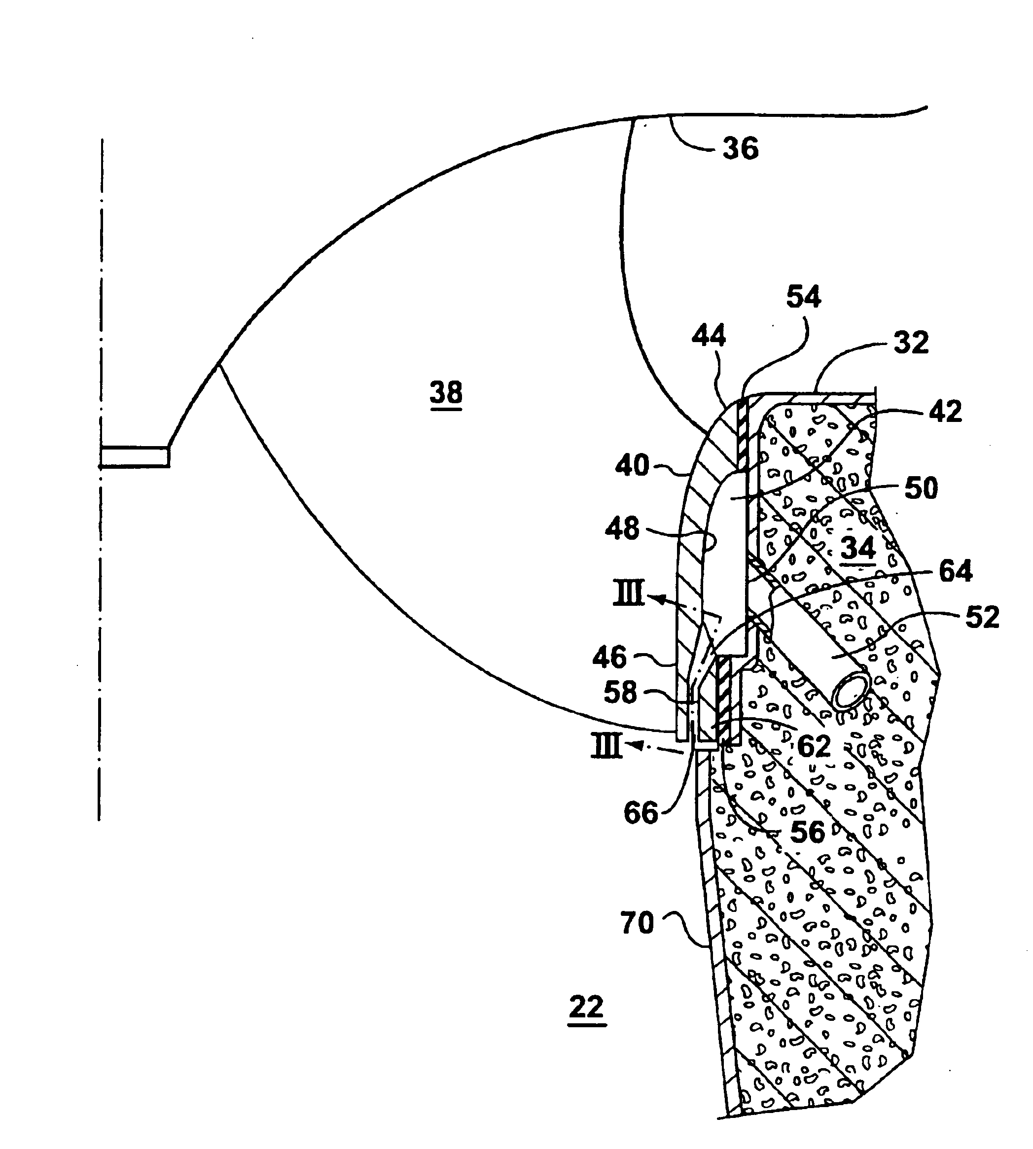
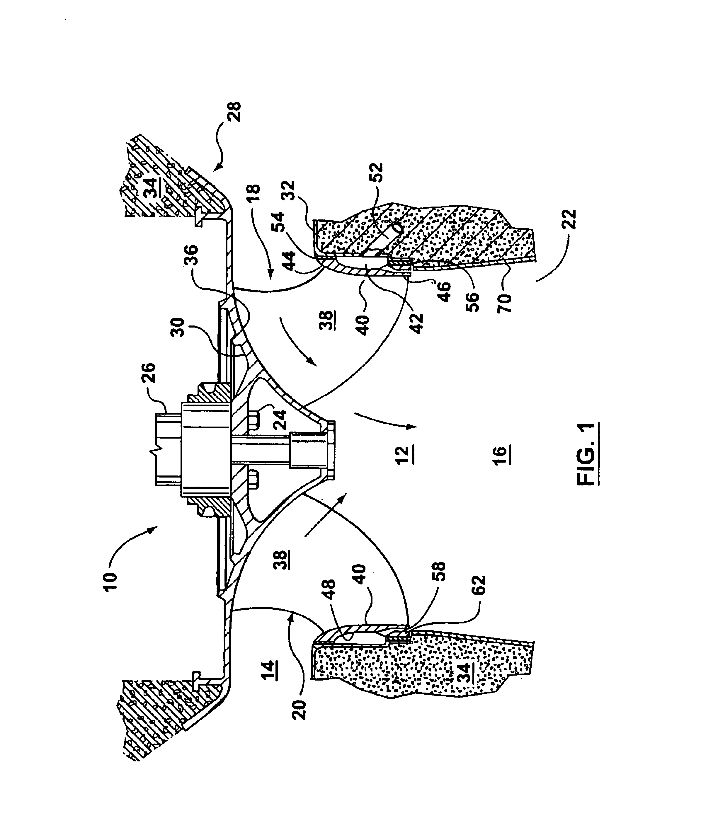
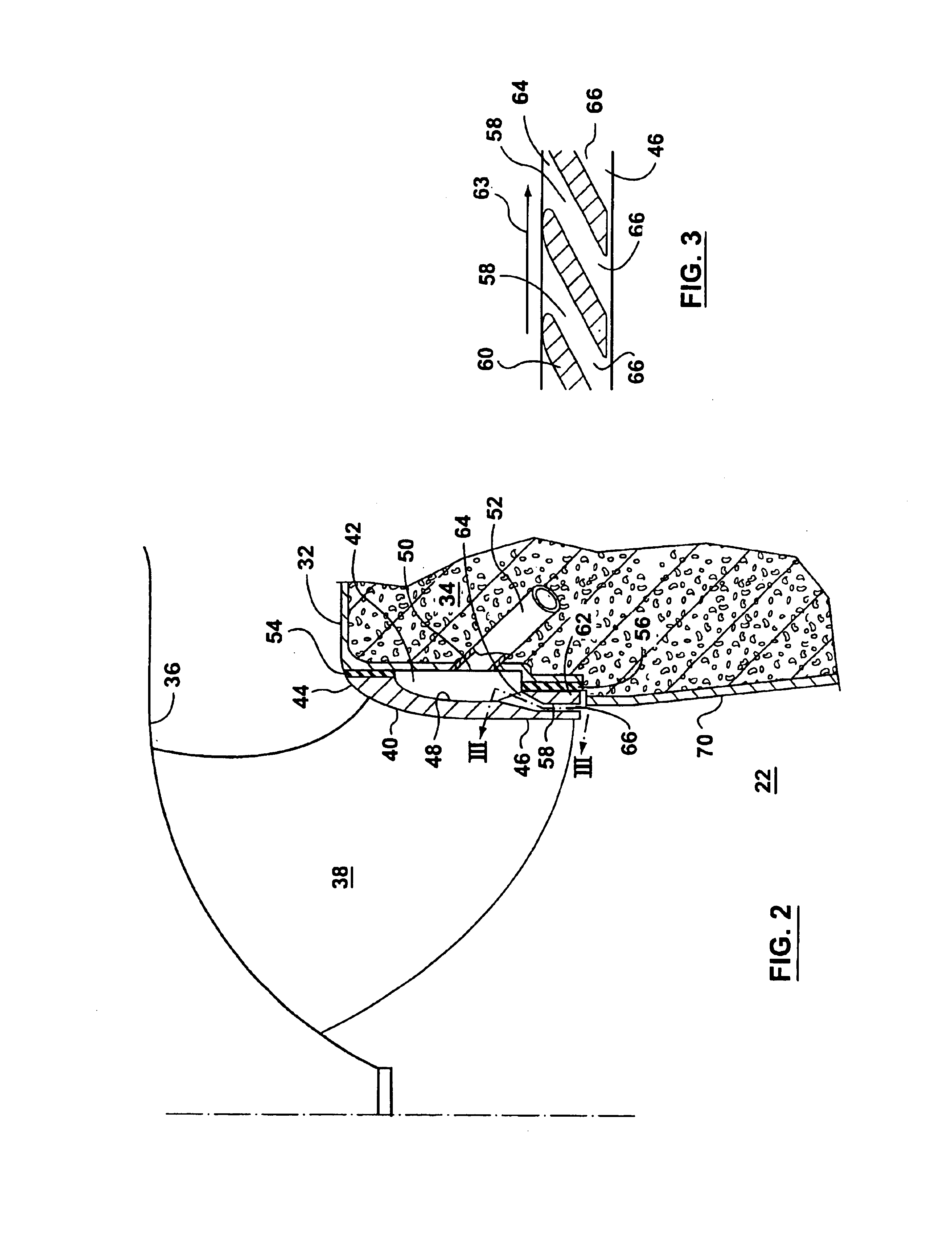
Referring to FIGS. 1 and 3, a turbine installation 10 is illustrated for use in the generation of hydroelectricity. The installation 10 has a water passageway 12. Water flows from an inlet 14 of passageway 12 to an outlet 16 located at a lower elevation. The water passageway 12 passes through a Francis turbine 18 having a runner 20 and a draft tube 22. The runner 20 is secured by bolts 24 to a shaft 26 transmitting energy to a generator (not shown). The turbine 18 is mounted in a stationary casing 28 having a head cover 30 and a bottom stationary discharge ring 32. The head cover 30, discharge ring 32 and draft tube 22 are embedded in concrete foundation 34.

Runner 20 is rotatably mounted in casing 28 and has a crown 36 and a plurality of circumferentially spaced runner blades 38 extending therefrom to an enclosing...


PUM


Abstract

A hydraulic turbine is adapted to introduce oxygen into a water flowing through a water passageway of a turbine. The turbine has a circumferential chamber formed between a rotating band and a stationary discharge ring. The chamber has a gas admission aperture for receiving an oxygen containing gas into the chamber. A downstream end portion of the band has a plurality of spaced apart vanes providing chamber outlet passageways between the vanes and through the band. The vanes are configured to rotate with the band and to draw the oxygen containing gas and water from the chamber through the outlet passageways in the band and into the water passageway.

Description

FIELD OF THE INVENTIONThe present invention relates to a hydraulic turbine and, in particular, to a turbine adapted to increase the dissolved oxygen content of water flowing through the turbine.BACKGROUND OF THE INVENTIONThe oxygen levels of water discharged from hydraulic turbines used in hydroelectric installations have been known to provide an environmental problem due to the discharged water having relatively low levels of dissolved oxygen. The problem is more predominant in the summer months. During the summer months, thermal stratification of water in an upstream water reservoir creates warmer water near the surface having relatively high dissolved oxygen and colder water near the bottom of the reservoir having relatively lower dissolved oxygen. Because the water utilized by the turbines is usually taken from the bottom of the reservoir, this water presents a potentially environmental hazard when discharged downstream by the turbines.In the building of new hydroelectric instal...

Claims


Application Information

Patent Timeline
Patent Type & Authority Patents(United States)
IPC IPC(8): F03B3/12F03B3/00F03B11/00
CPCF03B3/125F03B11/002Y02E10/226Y02E10/223Y02E10/20
Inventor DESY, NORMAND
Owner GENERAL ELECTRIC CANADA INC A CO OF CANADA
Learn More