
Power adapter

a power adapter and power connector technology, applied in the direction of coupling device connection, process and machine control, instruments, etc., can solve the problem of the height difference between the bottoms of the connector and the electrical device, and achieve the effect of safe use and convenient carrying

Inactive Publication Date: 2005-02-08
DELTA ELECTRONICS INC
View PDF5 Cites 8 Cited by
  • Summary
  • Abstract
  • Description
  • Claims
  • Application Information

AI Technical Summary

Benefits of technology

It is an object of the present invention to provide a power adapter for using safely and carrying conveniently.
It is another object of the present invention to provide a power adapter with a height difference design for holing and forcing easily and increasing the heat-dissipating efficiency of the electrical device and the connector.
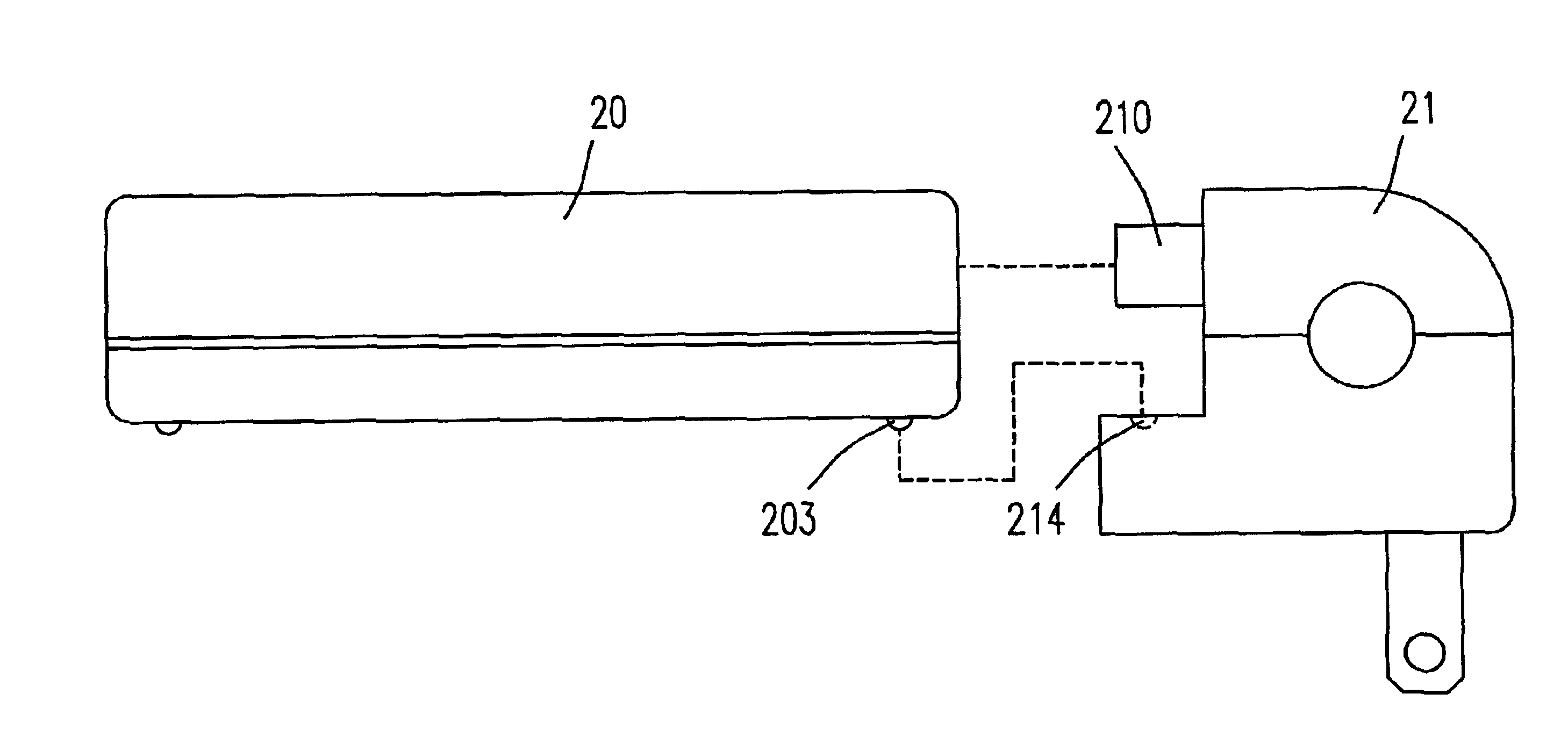
Preferably, when the conducting slices are plugged in the exterior AC receptacle, a space is formed below the bottom of the electrical device by the height difference, which is beneficial for holding and forcing by a user and increases the heat-dissipating efficiency of the electrical device and the connector.
Preferably, the connector further includes at least one pit (or knob) and the electrical device further includes at least one knob (or pit) for fixing the position and preventing unfastening of the connector and the electrical device.
Preferably, when the conducting slices are plugged in the exterior AC receptacle, a space is formed below the bottom of the electrical device by a height difference between the bottoms of the connector and the electrical device, which is beneficial for holding and forcing by a user and increases the heat-dissipating efficiency of the electrical device and the connector.
Preferably, the connector further includes at least one pit (or knob) and the electrical device further includes at least one knob (or pit) for fixing the position and preventing unfastening of the connector and the electrical device.

Problems solved by technology

In addition, there is a height difference between the bottoms of the connector and the electrical device.

Method used


Image

  • Power adapter
  • Power adapter
  • Power adapter

Examples


Embodiment Construction

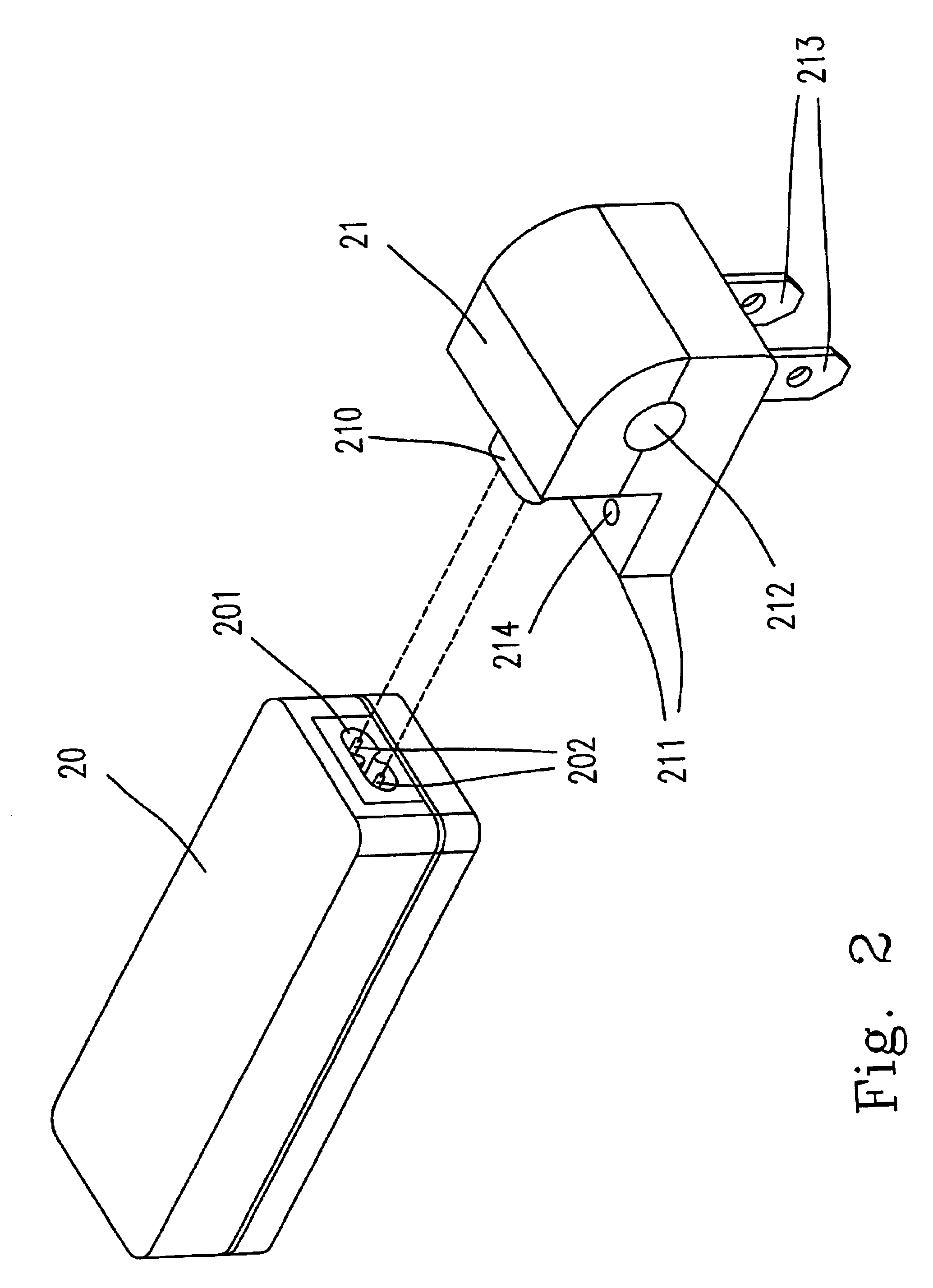
Please refer to FIGS. 2 and 3 showing the structure of the power adapter according to a preferred embodiment of the present invention. A power adapter includes an electrical device 20 and a connector 21 for connecting an electric appliance to an AC main power. The electrical device 20 is a power supply or a charger. The power input / output end of the electrical device 20 has two metal prongs 202 disposed in a cavity 201. Preferably, the two metal prongs are two metal sticks, and the number of the metal prongs are variable to meet the requirements or the standards in different countries.

Please refer to FIG. 2 and FIG. 3. The connector 21 has a body 217 and two recesses (not shown) disposed on a protruding portion 210. The two recesses can sleeve the two metal prongs 202, such that the connector 21 and the electrical device 20 can be tightly assembled and electrically connected (as shown in FIG. 3) so as to connect the electric appliance to the AC main power. The cavity 201 having two ...


PUM


Abstract

The present invention discloses a power adapter for connecting an electric appliance to an AC main power. The power adapter includes an electrical device having at least two metal prongs in the power input / output end thereof, and a connector having at least two recesses for sleeving the metal prongs respectively and electrically connecting the connector to the electrical device. In addition, there is a height difference between the bottoms of the connector and the electrical device. Moreover, each of the two sides of the connector includes a hollow region respectively for the convenience of assembling and disassembling the connector and the electrical device. Furthermore, there are pit-knob matching structures in the connector and the electrical device for fixing the position and preventing unfastening of the connector and the electrical device in the assembling state.

Description

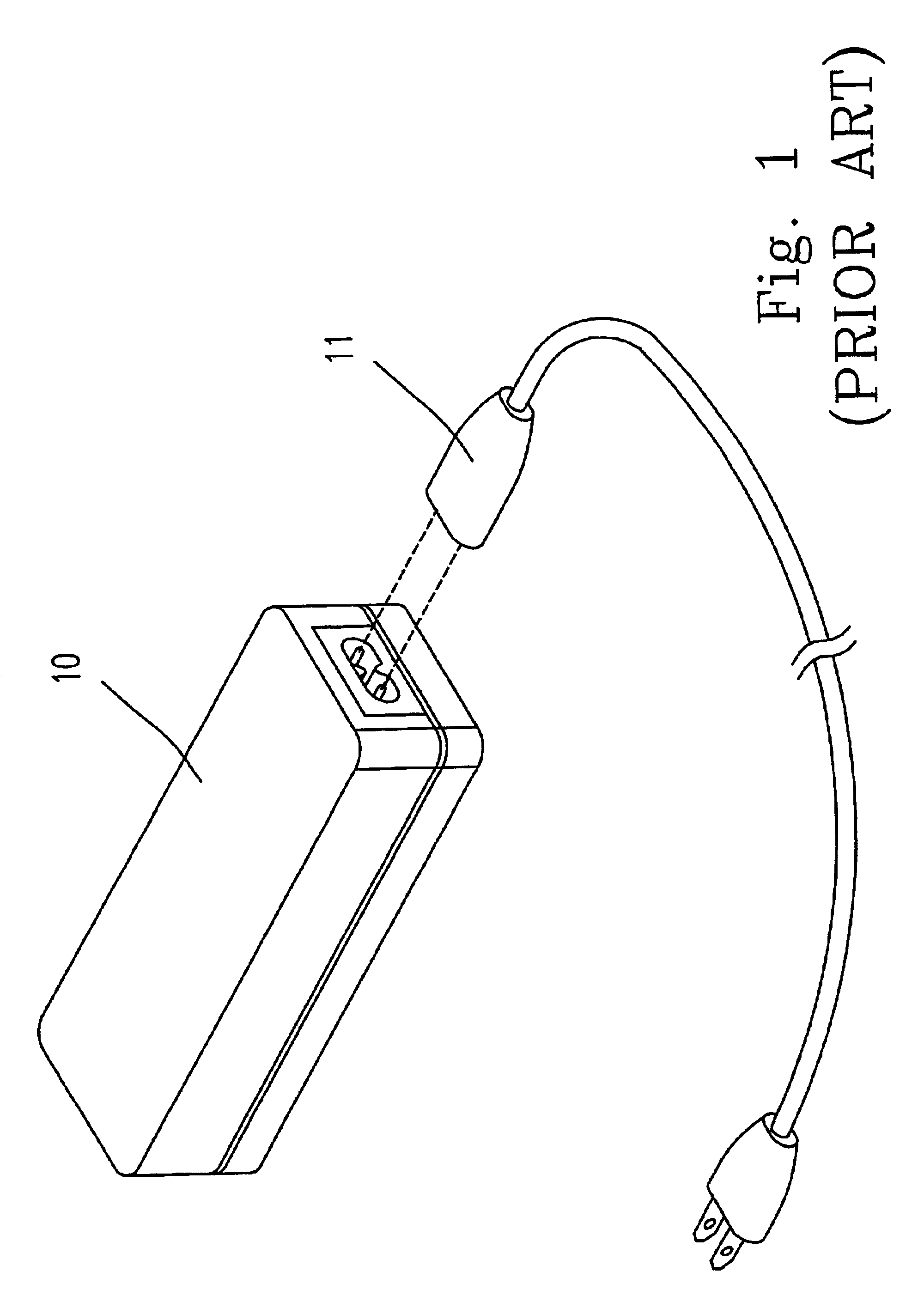
FIELD OF THE INVENTIONThis invention relates to a power adapter, and more particularly to a power adapter for connecting an electric appliance to an AC main power.BACKGROUND OF THE INVENTIONCurrently, electric appliances have been widely used in daily life. Many electric appliances such as portable electric appliances and mobile phones are more and more common in daily life, and these electric appliances have to be power supplied through the AC converting adapters.Please refer to FIG. 1. FIG. 1 is a schematical view showing the structure of the power adapter according to the prior art including an electrical device (such as a power supply or a charger) 10 and an AC cable 11. The electrical device 10 is connected to a power receptacle by the AC cable 11 to provide the main power for the electrical device 10. However, such way for connecting an electric appliance to an AC main power has the following disadvantages:1. Inconvenient to carry: It is inconvenient for a user to carry the AC...

Claims


Application Information

Patent Timeline
Patent Type & Authority Patents(United States)
IPC IPC(8): H01R31/06
CPCH01R31/06
Inventor LIN, SHENG-CHIEH
Owner DELTA ELECTRONICS INC
Learn More