
Bale accumulator

a bale accumulator and bale technology, applied in the field of bale accumulators, can solve the problems of failure to dump multiple bales, and achieve the effect of stable stacking of bales

Inactive Publication Date: 2005-02-08
PHIBER MFG
View PDF12 Cites 19 Cited by
  • Summary
  • Abstract
  • Description
  • Claims
  • Application Information

AI Technical Summary

Benefits of technology

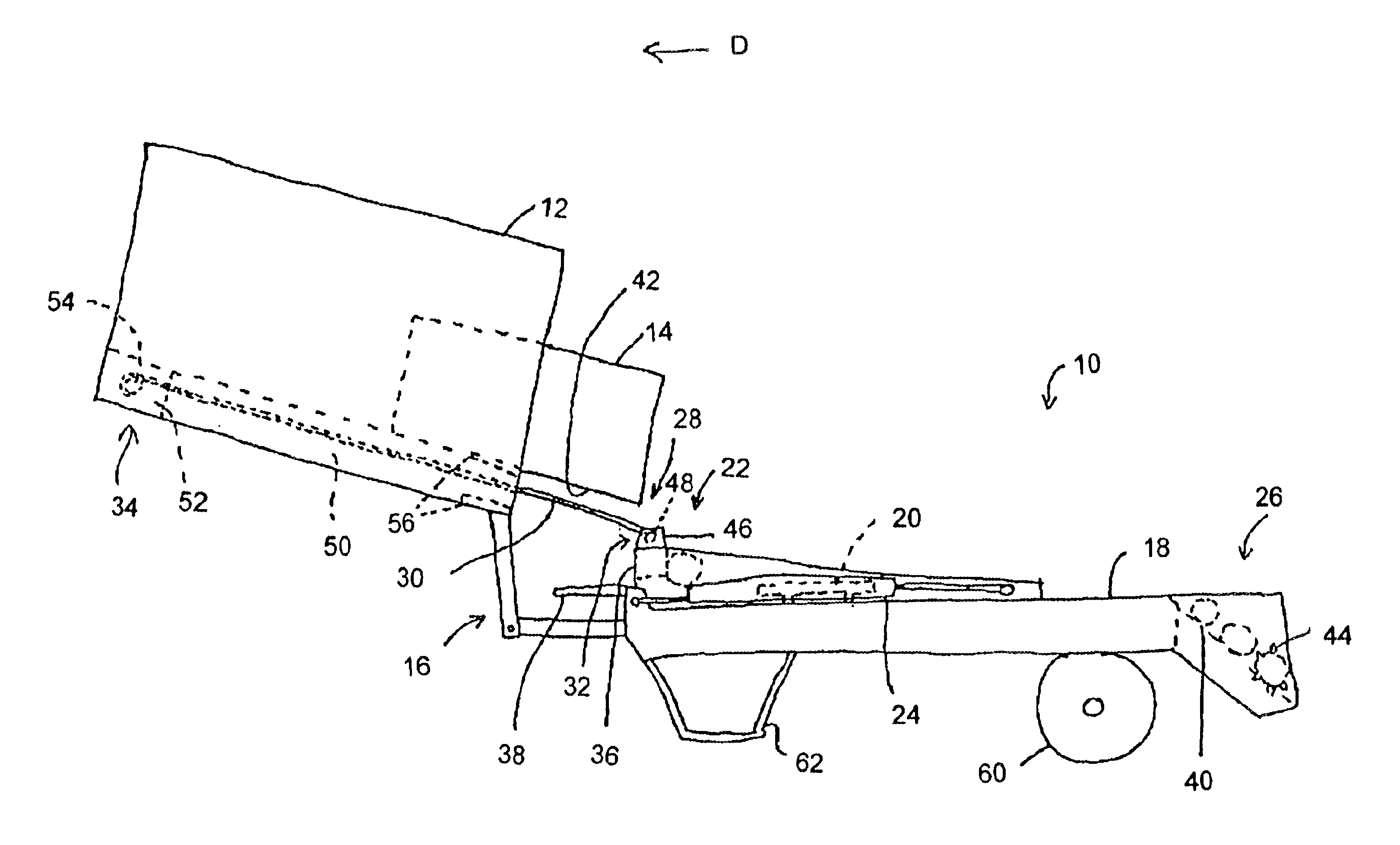
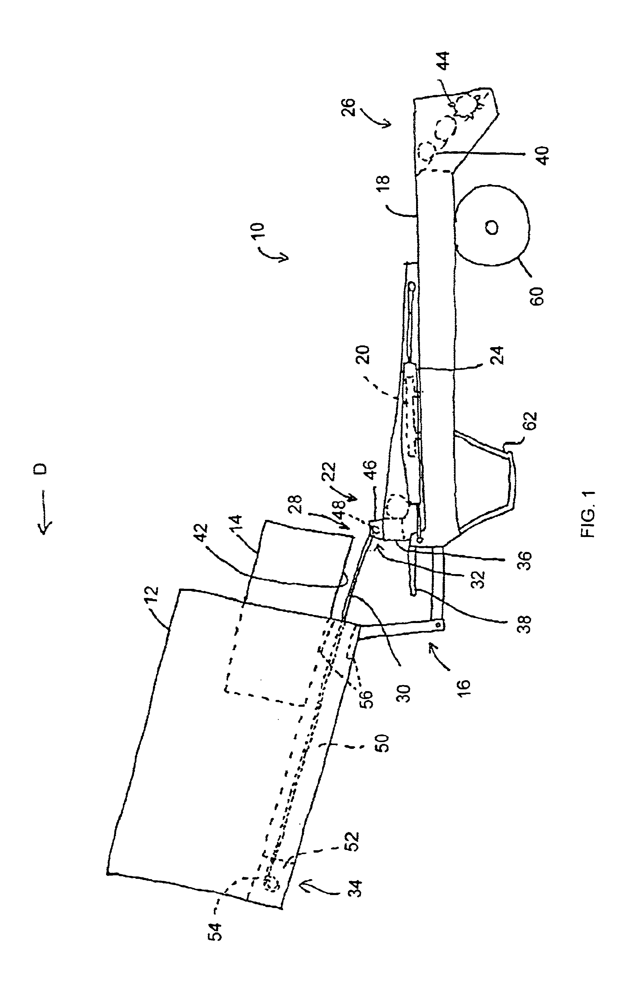
The rear bale support holds the bales off the ground during discharge from the platform. This limits the disruption of the bale array by differential ground friction on the different bales. The forward bale support supports a bale as it is extruded by the baler, to prevent the bale from dropping to the platform in front of the pusher.
In preferred embodiments of the present invention, the rear bale support comprises a series of parallel spaced rollers to engage bottom surfaces of the three bales and support the bales as they move in a rearward direction off of the accumulator. At least one of the rollers is preferably fitted with protuberances to engage the bottom surfaces of the bales to assist in moving the three bales off of the accumulator at the same speed so that they are deposited in the desired array on the ground.
It can be seen, therefore, that the present invention manipulates bales as desired, including automatically in two-bale arrangements, while allowing uninterrupted operation of the baler and deposition at any desired location. The present invention allows an operator to deposit multiple bales on the ground in an even arrangement without requiring shutting down the baler and manually repositioning the bales prior to pick-up, enabling stable stacking of bales on a truck or other transport. Also, while the present invention employs a pusher mechanism to move a bale rearwardly on the bale accumulator, the forward bale support ensures that the operator need not stop the baler operation until the bale accumulator has dumped its prior load of bales in order to return the mechanism to a position to receive the next load; rather, the next set of bales can be loading onto the platform while the previous set is dumped. Finally, the present invention allows the operator to dump the multiple bales in any desired location, not one determined solely by the time of filling the accumulator. The accumulator of the present invention can also be turned off and dump single bales over the back, while some other commercially available accumulators must be disconnected to allow this.

Problems solved by technology

A recurring problem with multiple-bale bale accumulators, however, is that they fail to dump the multiple bales in an even arrangement, usually requiring shutting down the baler and manually repositioning the bales prior to pick-up.
Another problem is that the mechanism employed to move a bale rearwardly on the bale accumulator often requires that the operator stop the baler operation during dumping of a load of bales and until the mechanism has returned to a position to receive the next load.
In addition, the design of most accumulators forces the operator to dump the multiple bales in a location determined by the time of filling the accumulator; this may be in a convenient location for pick-up but often it is not.

Method used


Image

  • Bale accumulator
  • Bale accumulator
  • Bale accumulator

Examples


Embodiment Construction

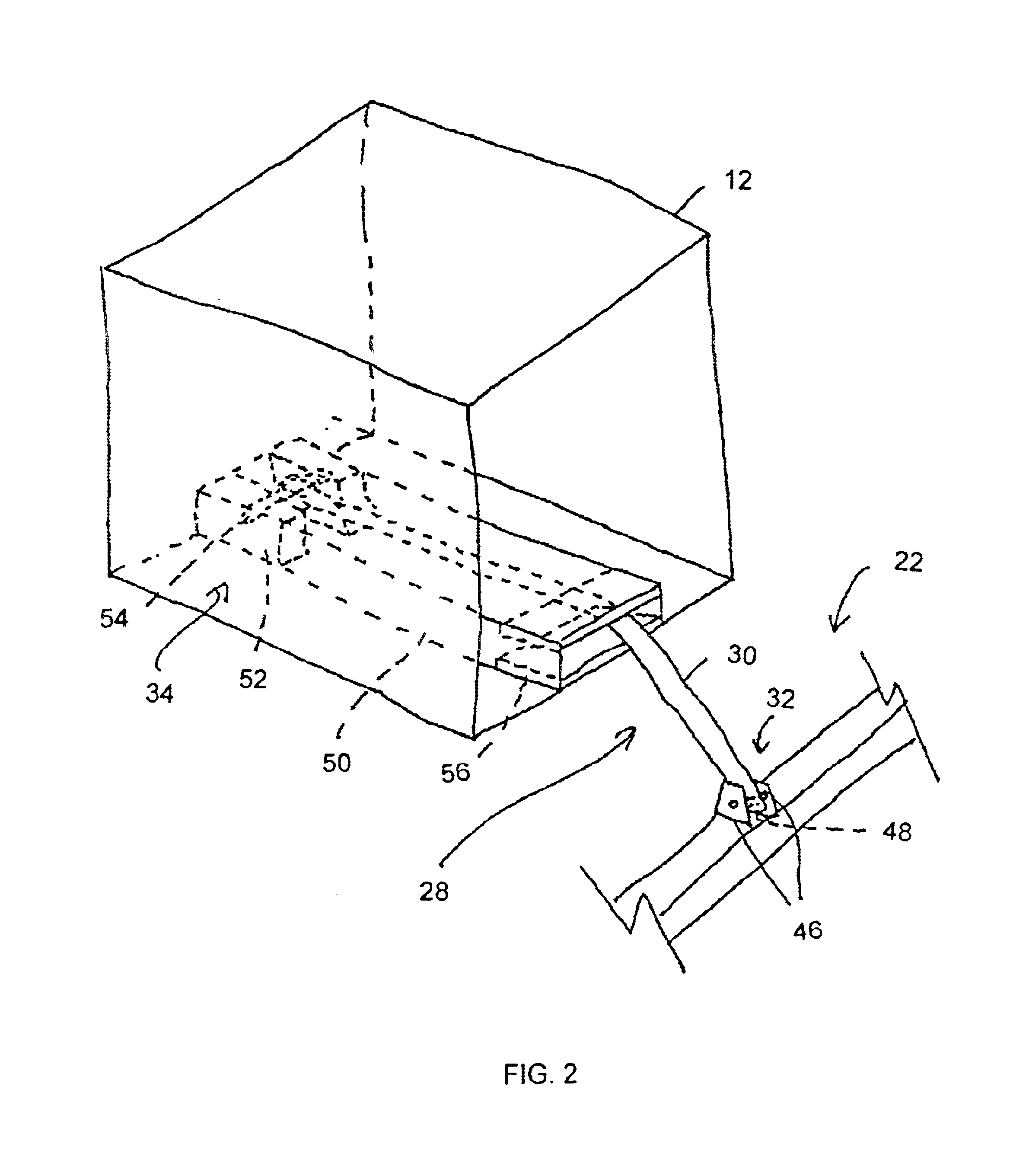
Referring now in detail to the accompanying drawings, there is illustrated an exemplary embodiment of the bale accumulator of the present invention generally referred to by the numeral 10, for use with a baler 12 for producing rectangular bales 14 of agricultural crops as the baler 12 traverses a field in a forward direction of travel, indicated by the arrow D in FIG. 1, and extruding the bales 14 longitudinally from a rear end of the baler 12. The baler 12 is depicted in simplified fashion, representing simply a means of producing bales 14 for receipt by the bale accumulator 10. Referring in particular to FIGS. 1 and 3, the accumulator 10 comprises a hitch 16 for connecting the accumulator 10 to the rear end of the baler 12, a platform 18 for receiving bales extruded by the baler 12, positioning means 20 for arranging the bales 14 in a selected array on the platform 18, a pusher 22 mounted for movement longitudinally of the platform 18, a rear bale support 26, and a forward bale su...


PUM


Abstract

A bale accumulator is provided for use with a baler for producing rectangular bales of agricultural crops, the accumulator comprising a hitch for connecting the accumulator to the baler, a platform for receiving bales extruded by the baler, a positioning device for arranging the bales in a selected array on the platform, a pusher mounted for movement longitudinally of the platform, an actuator on the accumulator for moving the pusher rearwardly along the platform to move bales along the platform, a rear bale support rearwardly of the platform for supporting bales as they are moved off of the platform by the pusher, and a forward bale support extending forwardly from the pusher for supporting a bale in front of and above the pusher as it is extruded from the baler. The bale accumulator manipulates bales as desired while allowing uninterrupted operation and dumping at any desired location.

Description

FIELD OF THE INVENTIONThe present invention relates to apparatus for handling bales of agricultural crops, and more particularly to bale accumulators.BACKGROUND OF THE INVENTIONBalers and similar machines have been employed for many years in the agricultural industries for gathering and packaging agricultural crops, for example hay, into bales. The bales are then used for purposes including feeding livestock. As baler technology developed, and particularly with the advent of balers for producing large rectangular bales, bale accumulators were produced to collect the bales generated by a baler, position the bales on the ground in a selected array or pattern, for pick-up by another machine, for example a bale grab. U.S. Pat. No. 4,053,064 to Stewart, for example, discloses such a hay bale collector, wherein bales are shifted into alternating compartments, the entire load dumped when the compartments are filled by allowing the bales to come into frictional engagement with the ground su...

Claims


Application Information

Patent Timeline
IPC IPC(8): A01D85/00
CPCA01D85/005A01D2085/008A01D2085/007
Inventor BERGEN, HARVEY G.FRIESEN, A. PHIL
Owner PHIBER MFG
Learn More