
Layer 2 funnel in fan out network device

a network device and funnel technology, applied in the field of funnels in network devices, can solve problems such as heavy traffi

Inactive Publication Date: 2005-02-01
CISCO TECH INC
View PDF19 Cites 57 Cited by
  • Summary
  • Abstract
  • Description
  • Claims
  • Application Information

AI Technical Summary

Benefits of technology

These and other features and advantages of the present invention will be presented in more detail in the following d

Problems solved by technology

Since all network traffic is seen by the network appliance, very heavy traffic is experienced on the interface that connects the network appliance to all of the subnetworks.

Method used


Image

  • Layer 2 funnel in fan out network device
  • Layer 2 funnel in fan out network device

Examples


Embodiment Construction

A detailed description of a preferred embodiment of the invention is provided below. While the invention is described in conjunction with that preferred embodiment, it should be understood that the invention is not limited to any one embodiment. On the contrary, the scope of the invention is limited only by the appended claims and the invention encompasses numerous alternatives, modifications and equivalents. For the purpose of example, numerous specific details are set forth in the following description in order to provide a thorough understanding of the present invention. The present invention may be practiced according to the claims without some or all of these specific details. For the purpose of clarity, technical material that is known in the technical fields related to the invention has not been described in detail in order not to unnecessarily obscure the present invention.

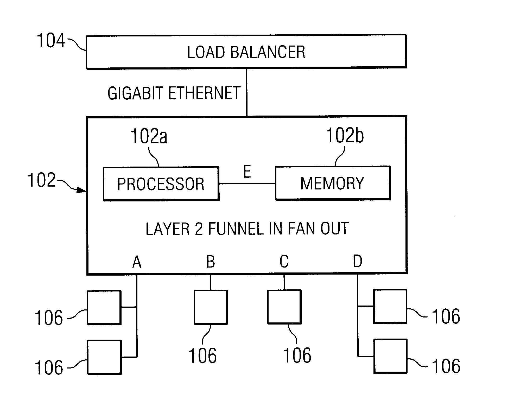
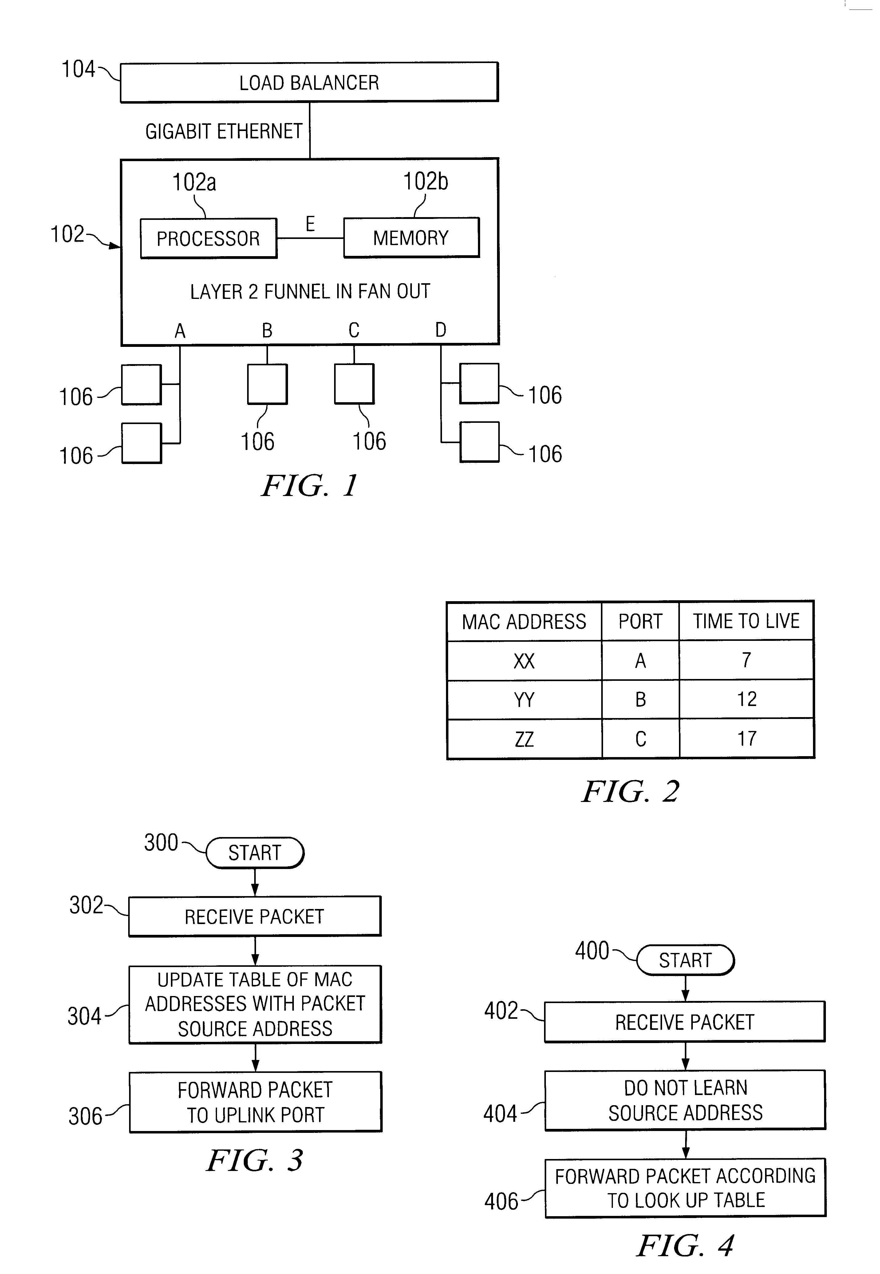
For the purpose of example, the funnel in fan out device described below is described as directing pack...


PUM


Abstract

A funnel in fan out network device includes a fast uplink port operating at a first data rate. A plurality of slow ports operate at a second data rate. The second data rate is slower than the first data rate. A processor is configured to direct a packet received on one of the slower ports directly to the fast uplink port without looking up the destination address of the packet.

Description

FIELD OF THE INVENTIONThe present invention relates generally to a data link layer (layer 2) multi-port bridge or switch that transfers packets between different networks. More specifically, a funnel in fan out device is disclosed that includes multiple ports including an uplink port designated to receive all packets sent from the remaining ports.BACKGROUND OF THE INVENTIONThe problem of networking a set of devices has been divided into layers. The bottom layer is a physical layer. It handles the actual physical connections between devices. The second layer is the data link layer. It describes how the data is formatted on the physical medium that connects the devices. The third layer is the network layer. It handles cases where there is greater than one connection per machine. The fourth layer is the transport layer. This determines that all of the messages from a source reach the destination reliably and in an unduplicated fashion. Often the second layer is subdivided into a Logica...

Claims


Application Information

Patent Timeline
IPC IPC(8): H04L12/56
CPCH04L45/00
Inventor WONG, BRUCE F.
Owner CISCO TECH INC
Learn More