
Wire dot printer head and wire dot printer

a printer head and wire dot technology, applied in the field of wire dot printers and printer heads, can solve the problems of deteriorating printing quality, unstable swinging movement of armatures, and intensive oscillation of printing, and achieves high impact force, high speed printing, and the effect of suppressing an abrasion of a surfa

Inactive Publication Date: 2005-02-01
TOSHIBA TEC KK
View PDF9 Cites 34 Cited by
  • Summary
  • Abstract
  • Description
  • Claims
  • Application Information

AI Technical Summary

Benefits of technology

Taking the above problems into account, an objective of the present invention is to provide a wire dot printer head and a wire dot printer which are capable of suppressing an abrasion of a surface of a yoke for obtaining a high speed printing and a high impact force, preventing a deterioration in printing quality, and obtaining a printing performance being stable for a long period of time.

Problems solved by technology

However, with speed-enhancement in printing in recent years, the armature 102 has to swing between the printing position and the waiting position, for example, 2,500 times per second, thereby causing an intensive oscillation during the printing.
Consequently, this may become a factor which deteriorates a printing quality.
Then, it may also cause unstable swinging movement of the armature 102.

Method used


Image

  • Wire dot printer head and wire dot printer
  • Wire dot printer head and wire dot printer
  • Wire dot printer head and wire dot printer

Examples


Embodiment Construction

Hereinafter, the preferred embodiments of the present invention will be explained with reference to FIG. 1 to FIG. 5.

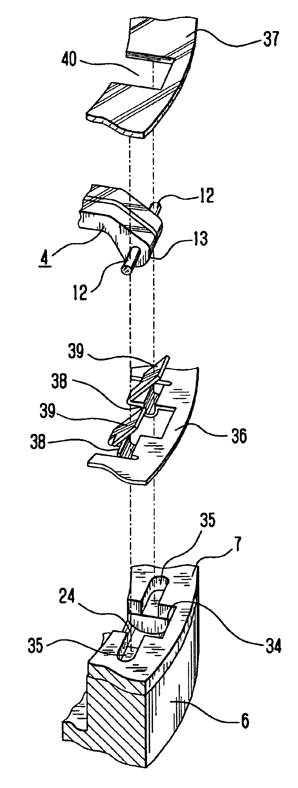
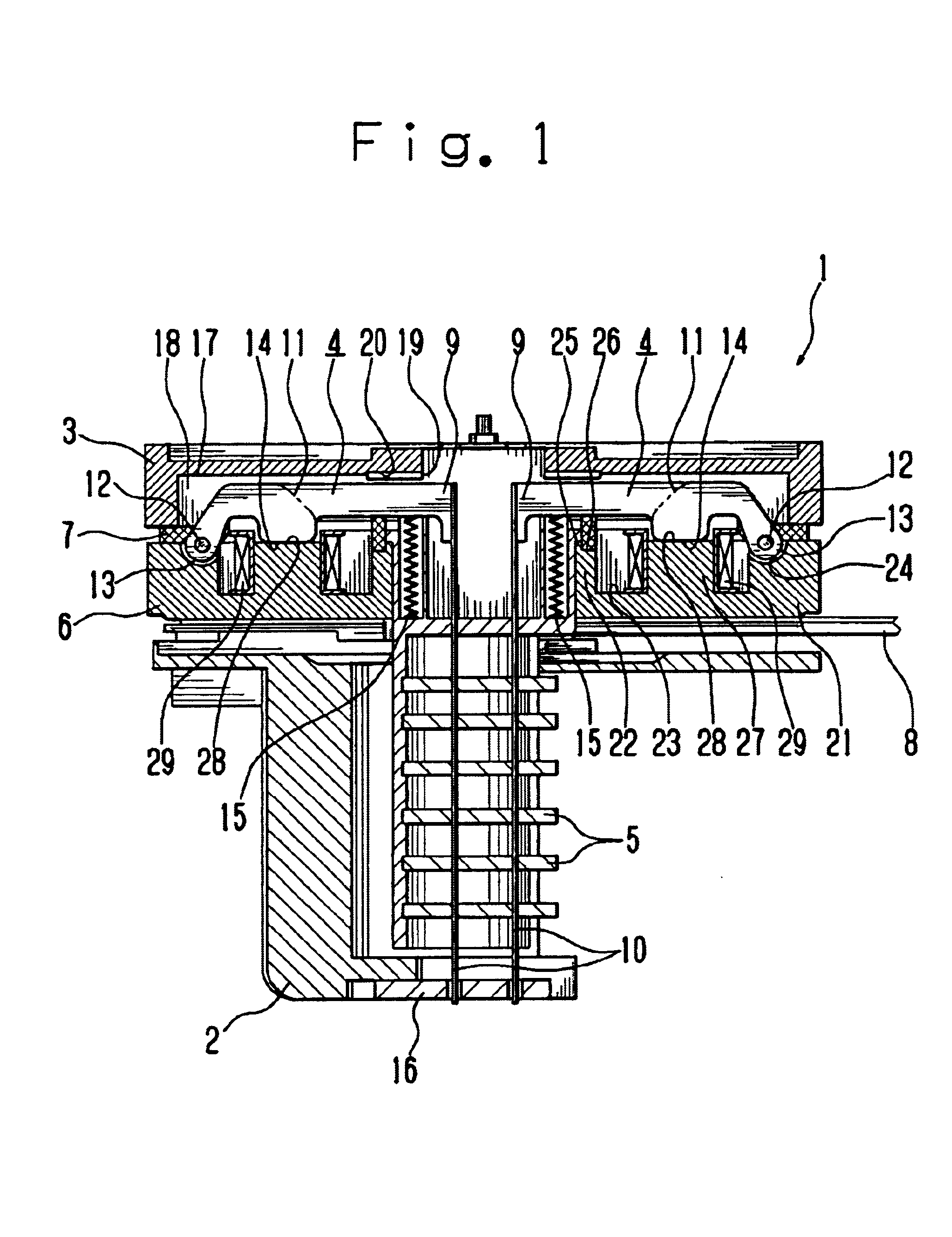
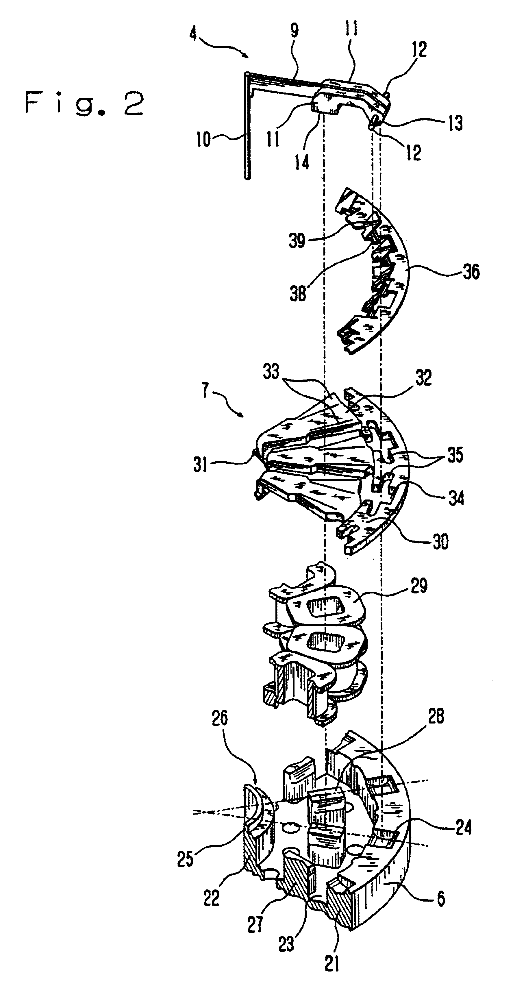
Firstly, an overall configuration of the wire dot printer head will be explained referring to FIG. 1 to FIG. 4. FIG. 1 is a central longitudinal sectional front view schematically showing a part of a wire dot printer head of the present embodiment, FIG. 2 and FIG. 3 are exploded perspective views schematically showing a part of the wire dot printer head, and FIG. 4 is a longitudinal sectional side view schematically showing a part of the wire dot printer head.

The wire dot printer head 1 has a front case 2 and a rear case 3, which are joined via fixing screws (not illustrated). Between the front case and the rear case, there are provided armatures 4, a wire guide 5, a yoke 6, an armature spacer 7 and a circuit board 8 or the like.

Each armature 4 comprises an arm 9, a printing wire 10 (hereinafter referred as “wire”), which is brazed on one end in the long direction of ...


PUM


Abstract

A wire dot printer head of the present invention is configured by being provided with an abrasion preventive member which surrounds an outer circumference of support shafts of a plurality of armatures, between an armature spacer having a plurality of cutouts for respectively accommodating the support shafts of the plural armatures that respectively support printing wires, and a yoke which holds the support shafts of the plural armatures with the armature spacer. With this structure, the support shafts of the armatures do not directly contact with the yoke owing to the abrasion preventive member, thereby restraining abrasion of a surface of the yoke, and preventing a deterioration of printing quality.

Description

BACKGROUND OF THE INVENTION1. Field of the InventionThe present invention relates to a wire dot printer head and a wire dot printer.2. Discussion of the BackgroundA wire dot printer head is an apparatus which swings an armature coupled with a wire for printing between a printing position and a waiting position, and when the armature is swung to the printing position, a tip end of the wire comes into collision with a print medium, such as a sheet of paper, whereby printing is carried out.As an example of such wire dot printer head as described above, in the gazette of Japanese Patent Application laid-open No. 2001-219586, there is disclosed an apparatus in which a magnetic flux induced by a coil around the armature to be swung generates a magnetic circuit for attracting the armature from the waiting position to the printing position, thereby executing a printing. As shown in FIG. 6 and FIG. 7, in the wire dot printer head 100 in the conventional art as described above, an armature 10...

Claims


Application Information

Patent Timeline
IPC IPC(8): B41J2/275B41J2/27B41J2/235
CPCB41J2/275
Inventor KAWAGUCHI, TAKAHIRO
Owner TOSHIBA TEC KK
Learn More