
Chip-type composite electronic component and manufacturing method thereof

a technology of composite electronic components and manufacturing methods, applied in the direction of positive temperature coefficient thermistors, emergency protective arrangements for limiting excess voltage/current, relays, etc., can solve the problem of fixed frequency characteristics of impedances and inability to chang

Inactive Publication Date: 2005-01-25
MURATA MFG CO LTD
View PDF7 Cites 9 Cited by
  • Summary
  • Abstract
  • Description
  • Claims
  • Application Information

AI Technical Summary

Benefits of technology

The present invention provides a small-sized chip-type composite electronic component that can change its impedance depending on temperature, and a manufacturing method thereof. The chip-type composite electronic component includes an inductor and a thermistor laminated together to define one chip, which allows for a smaller size and a more stable impedance characteristic. The resistance value of the thermistor changes drastically at a predetermined temperature, which can be used to control the circuit. The inductor and thermistor can be connected in series or in parallel, and an intermediate insulating layer can be used to prevent degradation and peeling of the components. The composite electronic component is useful in AC power supplies as a chip high-frequency filter or in DC power supplies as a chip thermistor.

Problems solved by technology

However, once a product is made, the frequency characteristic of the impedance is fixed and cannot be changed.

Method used


Image

  • Chip-type composite electronic component and manufacturing method thereof
  • Chip-type composite electronic component and manufacturing method thereof
  • Chip-type composite electronic component and manufacturing method thereof

Examples


Embodiment Construction

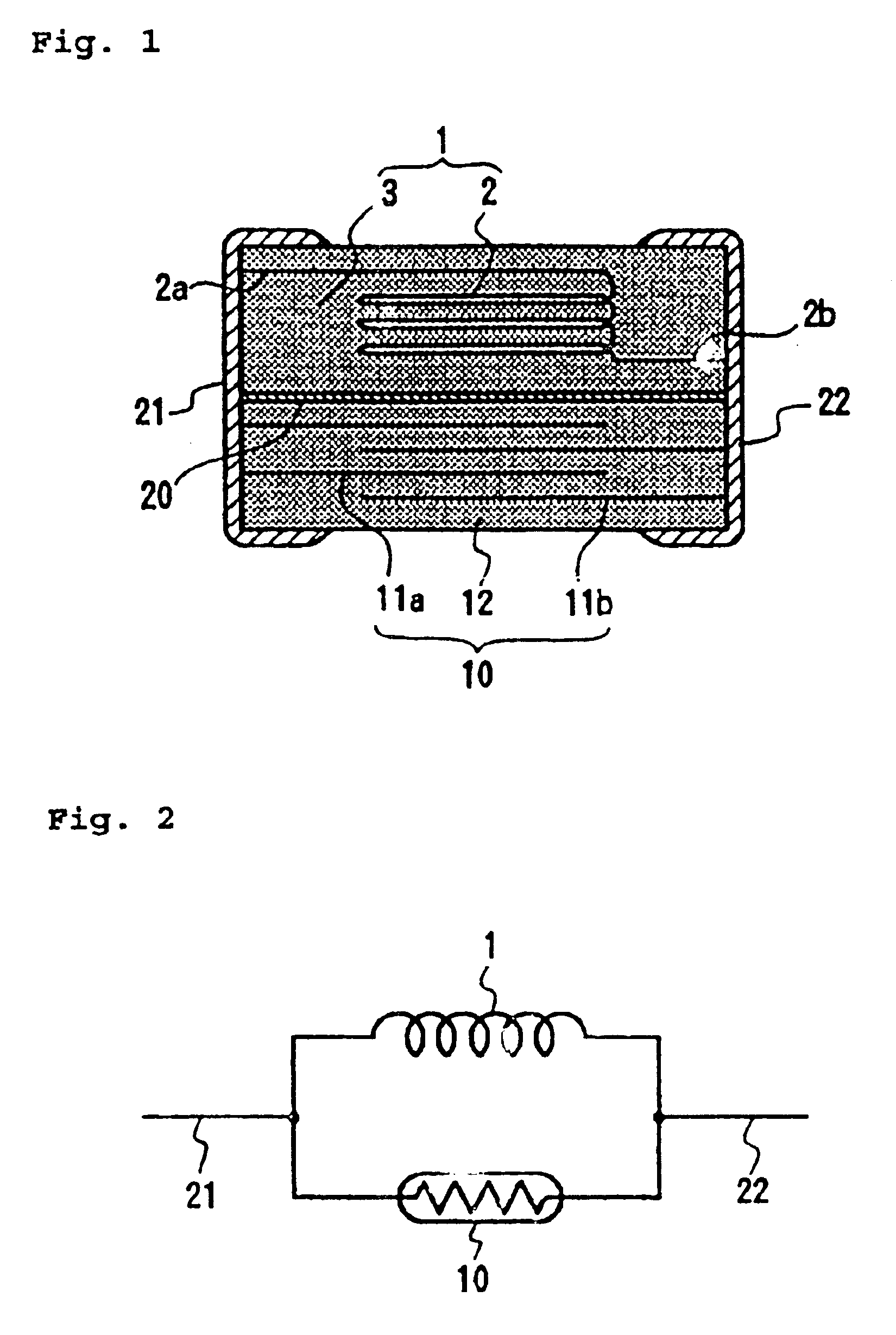
FIG. 1 shows a preferred embodiment of a chip-type composite electronic component according to the present invention.

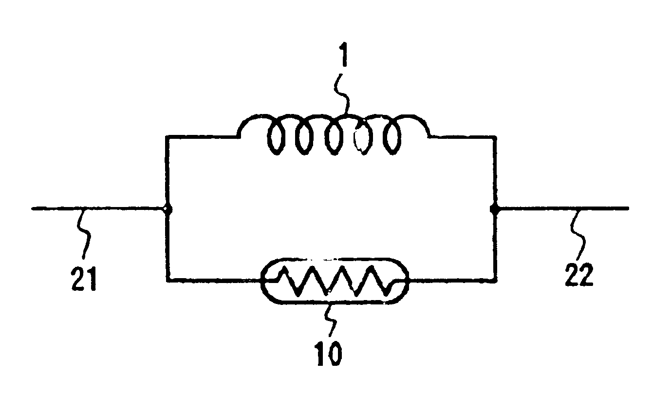
This composite electronic component includes an inductor 1 having the internal coil conductor 2 inside a ceramic main body 3 which includes a ferrite magnetic substance, and a thermistor 10 having internal electrodes 11a and 11b inside the ceramic main body 12 which includes the thermistor material with a predetermined resistance-temperature characteristic are laminated with an intermediate insulating layer 20 sandwiched therebetween. One end 2a of the internal coil conductor 2 and the internal electrode 11a are connected to an external electrode 21. The other end 2b of the internal coil conductor 2 and the internal electrode 11b are connected to an external electrode 22. As shown in FIG. 2, the inductor 1 and the thermistor 10 are connected in parallel.

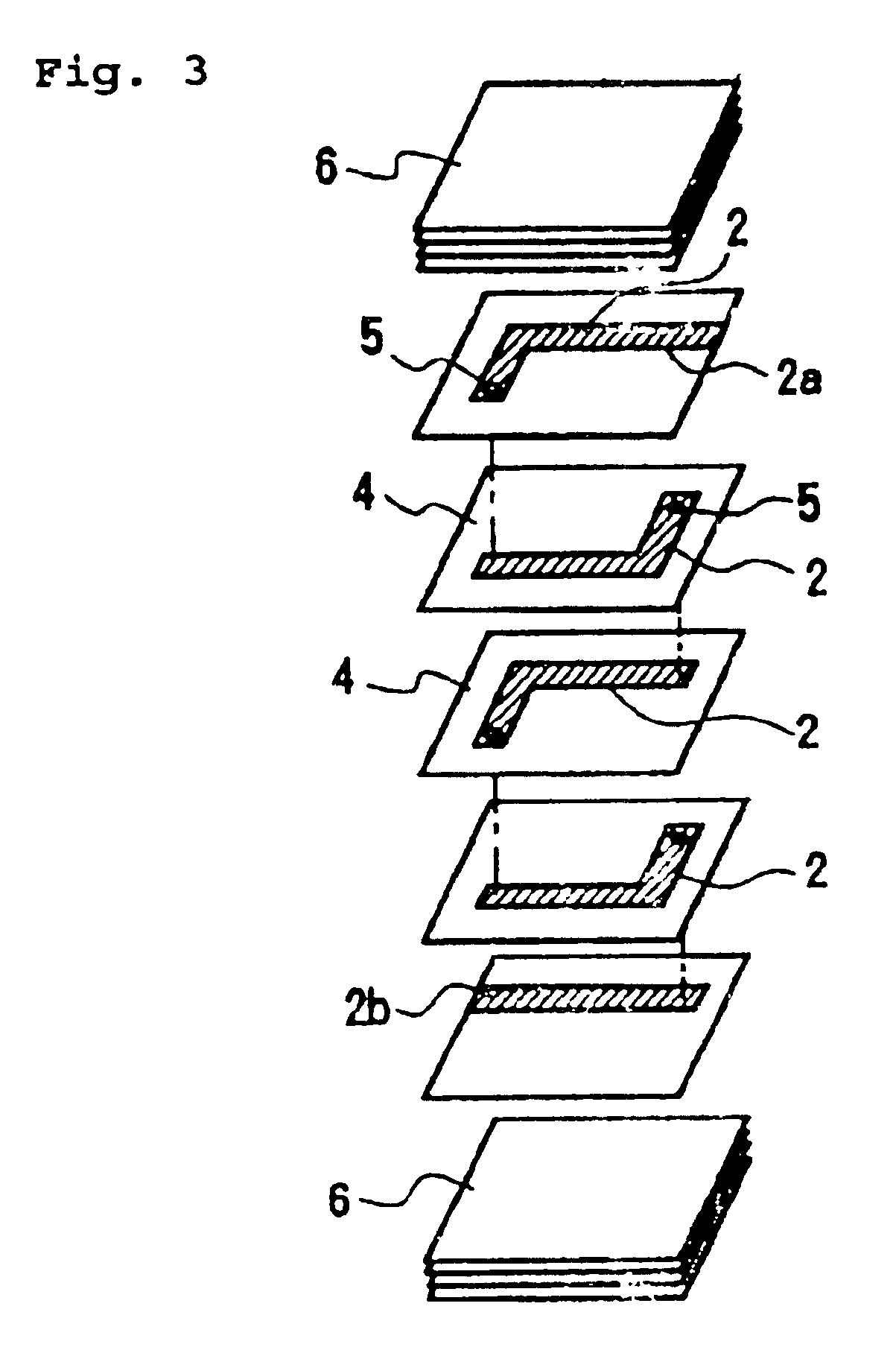
The inductor 1, as shown in FIG. 3, includes a spiral coil defined by laminating a plurality of ceramic layers 4 on ...


PUM

PropertyMeasurementUnit
temperatureaaaaaaaaaa
thicknessaaaaaaaaaa
impedanceaaaaaaaaaa

Abstract

An inductor obtained by laminating a plurality of ceramic layers having an internal coil conductor, and a thermistor obtained by laminating a plurality of ceramic layers having internal electrodes and having a predetermined resistance-temperature characteristic are laminated via an intermediate insulating layer. Both ends of the internal coil conductor of the inductor and the internal electrodes of the thermistor are connected to a pair of external electrodes. Thus, the inductor and the thermistor are connected in parallel.

Description

BACKGROUND OF THE INVENTION1. Field of the InventionThis invention relates to a chip-type composite electronic component and a manufacturing method thereof, and more particularly, to a composite electronic component of a chip inductor and a chip thermistor, and the manufacturing method thereof.2. Description of the Related ArtA conventional high frequency filter is described in Japanese Utility Model Pub. No. 6-50312 and includes a laminate-type chip inductor. In the chip inductor, laminated ceramic layers form a chip element, a wound coil wraps around the inside of the chip element to connect the coil conductor of a ceramic interlayer via a through-hole provided in a ceramic layer. Ends of the coil are connected to different external electrodes.In this kind of laminated type inductor, the impedance depends on the composition and the specific resistance of a ceramic material, the aperture-diameter dimension and the number of turns of a coil conductor, and the width and the material ...

Claims


Application Information

Patent Timeline
Patent Type & Authority Patents(United States)
IPC IPC(8): H01C7/18H01F27/00H01F27/40H01F17/00H01F41/04H01C1/00H01C1/16H01F27/28H01C7/02
CPCH01C1/16H01C7/18H01F17/0013H01F41/041H01F27/402H01F2027/406H01F2017/0026
Inventor KAWASE, MASAHIKOKIMOTO, HIDENOBU
Owner MURATA MFG CO LTD
Learn More