
Tailboom-stabilized VTOL aircraft

a tailboom and stabilizer technology, applied in the direction of vertical landing/take-off aircraft, launching weapons, transportation and packaging, etc., can solve the problems of limiting the diameter of paired co-planar rotors to less than half that of a comparable single, hovering propulsive force, and relying on the rotor's own inefficient lift, so as to control and stabilize horizontal flight, minimize the resistance to downwash

Inactive Publication Date: 2005-01-25
BALDWIN G DOUGLAS
View PDF19 Cites 114 Cited by
  • Summary
  • Abstract
  • Description
  • Claims
  • Application Information

AI Technical Summary

Benefits of technology

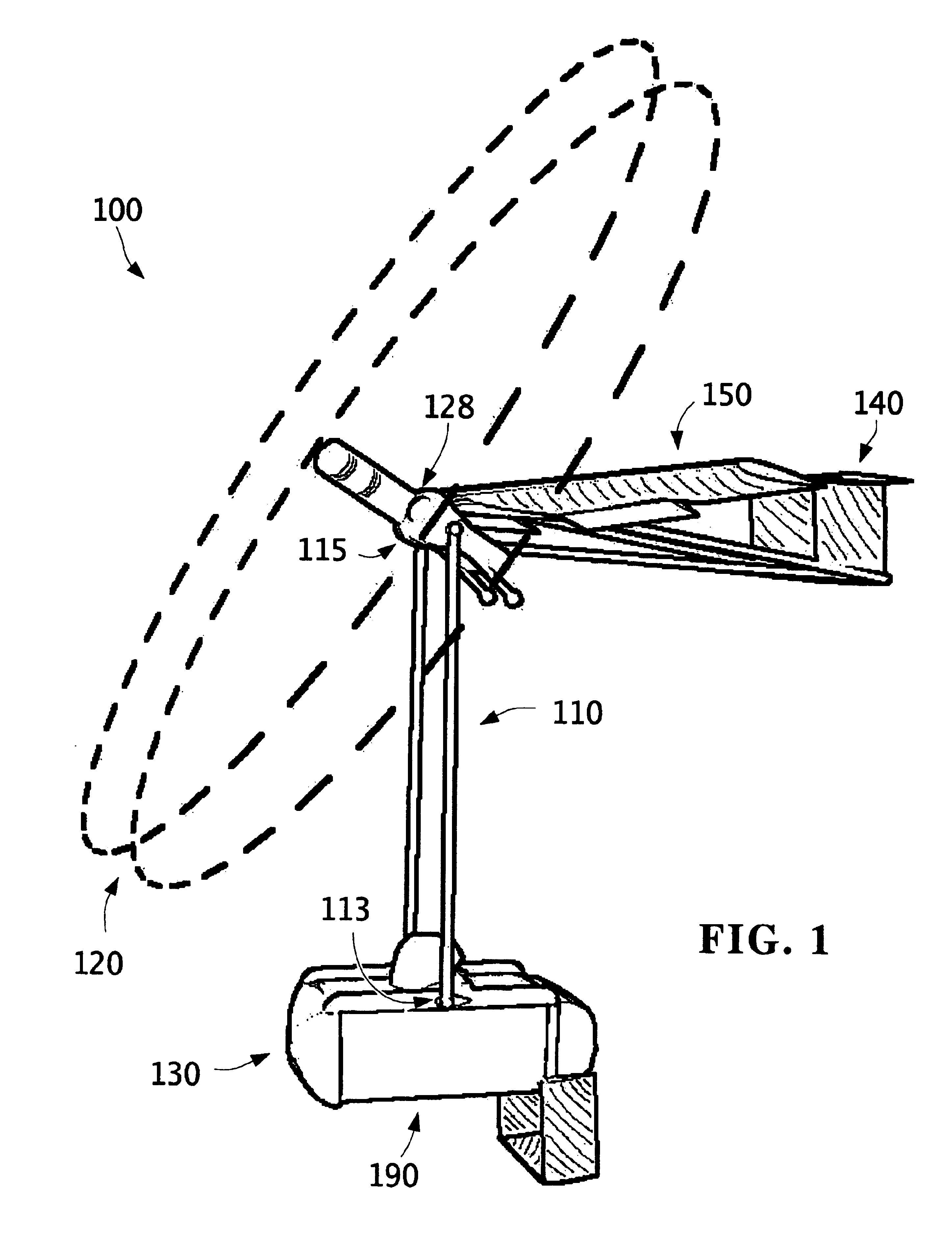
According to a particularly advantageous aspect of the invention, the lift unit can employ a rotor as a propulsion subsystem to provide an aerial motive force. In a mode of flight where such force is predominantly countering gravity (vertical flight or hover), the tailboom can hang from the lift unit in an orientation substantially parallel to the suspension structure and minimizing resistance to downwash from the lift unit. During a mode of flight in which the rotor (or other suitable propulsion subsystem) provides an aerial motive force predominantly parallel to the ground (horizontal flight), the tailboom can be orthogonal to the suspension structure, extending rearward in an orientation where it can develop pitching and yawing moments to control and stabilize horizontal flight.

Problems solved by technology

However, that configuration prevents such an aircraft from tilting its rotor for axial flow in horizontal flight with lift developed by a fixed wing.
Instead, it must rely on the rotor's own inefficient lift in edgewise airflow, with only enough rotor clearance available for a slight tilt to develop some horizontal airspeed.
This configuration has significant drawbacks, perhaps primarily that the prospect of blade interference with a centerline fuselage limits the diameter of paired co-planar rotors to less than half that of a comparable single rotor.
The use of paired smaller diameter rotors hurts efficiency, resulting in a hovering propulsive force that is less than 70% of what a single rotor would produce for comparable engine power, but with over 40% greater downwash velocity.

Method used


Image

  • Tailboom-stabilized VTOL aircraft
  • Tailboom-stabilized VTOL aircraft
  • Tailboom-stabilized VTOL aircraft

Examples


Embodiment Construction

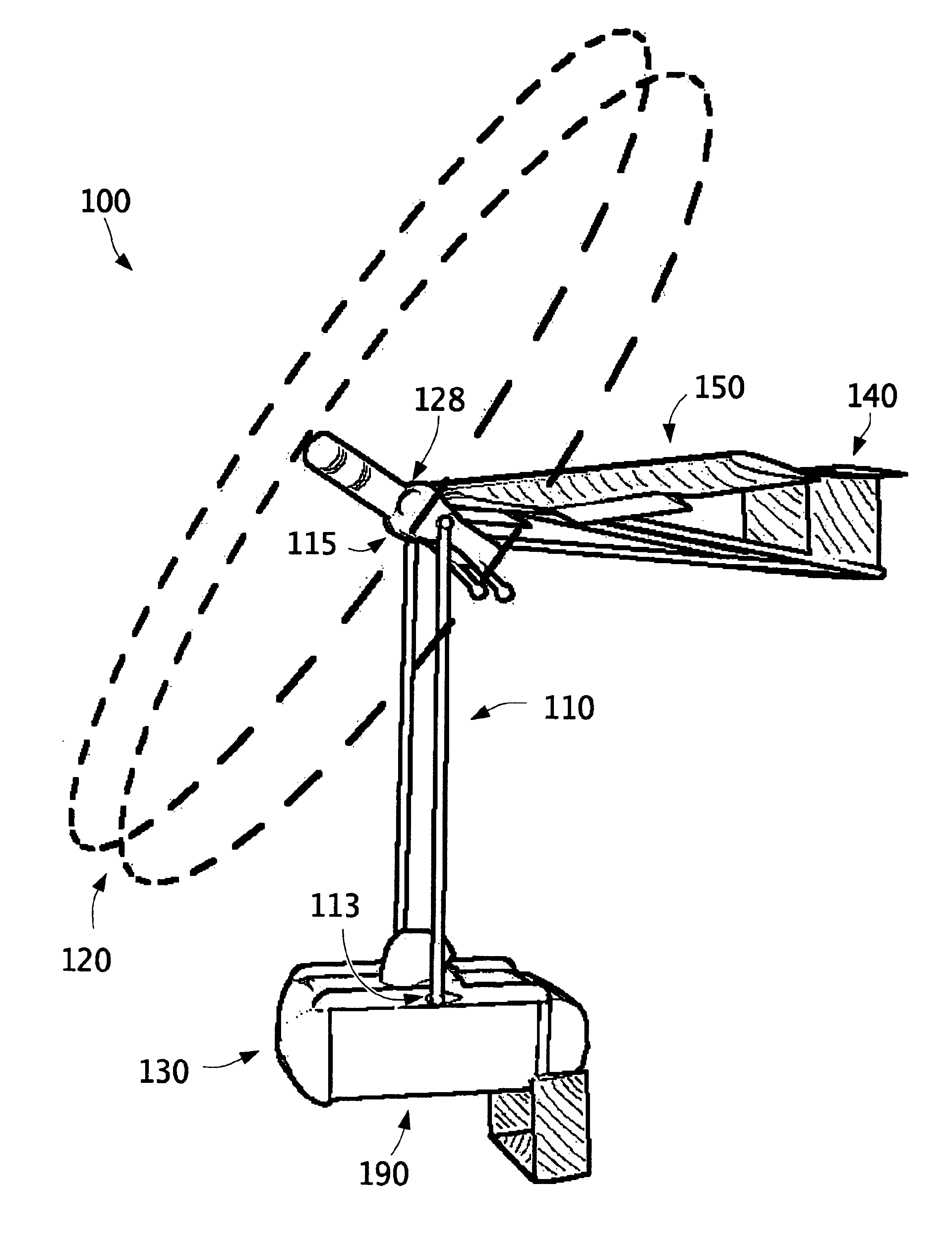
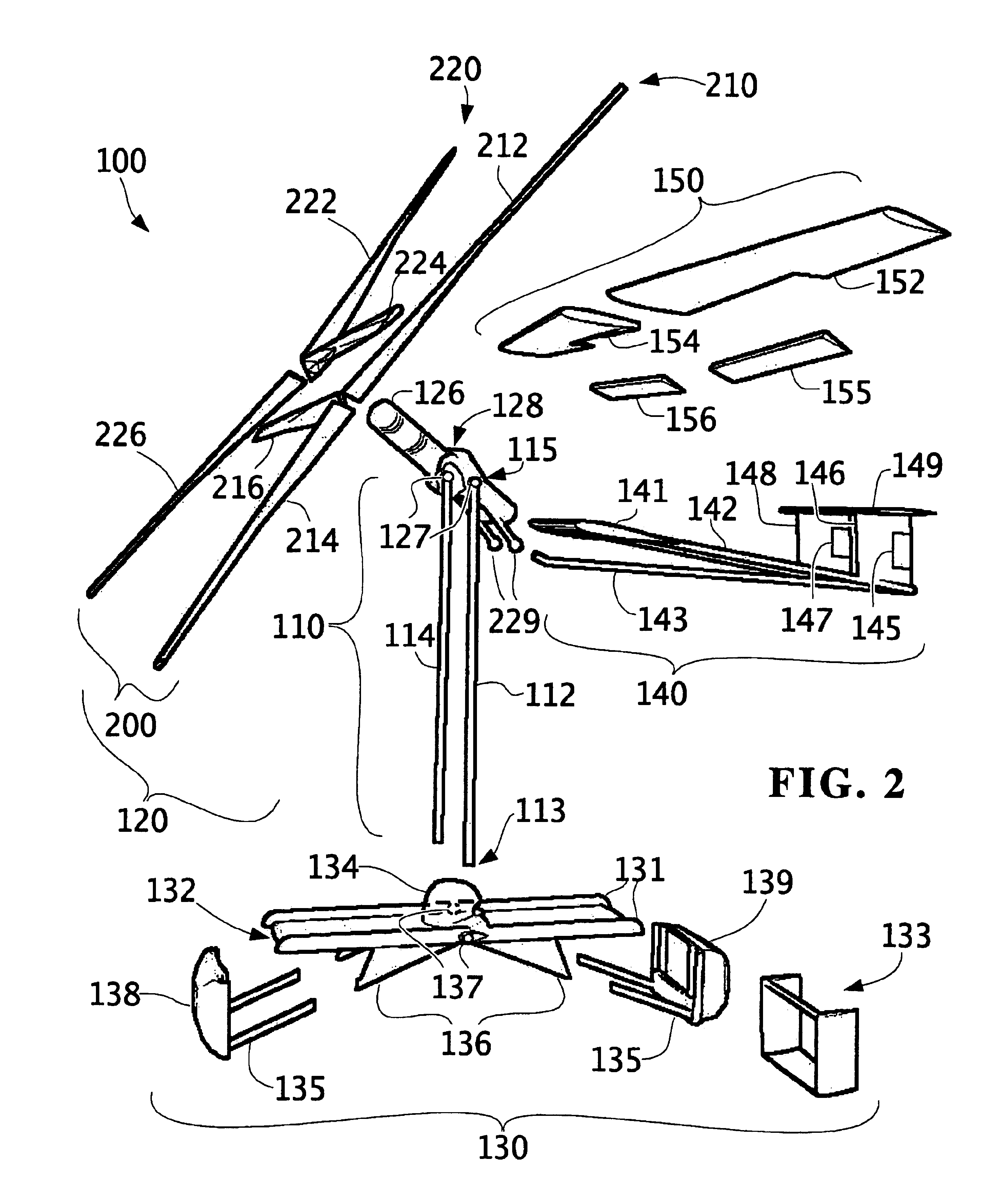
A VTOL flying craft according to various aspects of the present invention employs a tailboom to facilitate efficient, stable flight in both vertical and horizontal modes. As may be better understood with reference to FIG. 1, for example, one such flying craft 100 includes a suspension structure 110, a payload unit 130, and a lift unit 120 that includes a nacelle 128 and a tailboom 140. One end 113 of suspension structure 110 pivotally couples to lift unit 120 while an opposite end 115 pivotally couples to payload unit 130. Lift unit 120 further includes an aerodynamic lift structure 150.

A lift unit according to various aspects of the invention includes any heavier-than-air structure suitable for developing an aerial motive force including an upward component without exerting a corresponding force on any external supporting structure or relying on aerostatic buoyancy. A lift unit can develop such a force from a suitably configured propulsion subsystem, an aerodynamic lift structure, ...


PUM


Abstract

A disclosed flying craft includes a suspension structure having a first end and a second end, a lift unit, and a payload unit. The lift unit includes a nacelle and a tailboom, and pivotally couples to the first end of the suspension structure, and a payload unit couples to the structure's second end. Thus the tailboom can pivotally couple with respect to the payload unit, which advantageously permits the tailboom to assume an orientation desirable for a particular mode of flight. During vertical flight or hover, the tailboom can hang from the lift unit in an orientation that is substantially parallel to the suspension structure and that minimizes resistance to downwash from the lift unit. During horizontal flight, the tailboom can be orthogonal to the suspension structure, extending rearward in an orientation where it can develop pitching and yawing moments to control and stabilize horizontal flight. Advantageous variations and methods are also disclosed.

Description

BACKGROUND OF THE INVENTIONVertical Takeoff and Landing (VTOL) aircraft have long been considered desirable because of their ability to hover in flight and transition in and out of flight without a runway, in addition to flying in a horizontal direction. The aircraft's lift unit or units have propulsors (e.g., rotor, tiltable jet engines) that develop an aggregate aerial motive force. This aerial motive force can be viewed as the combination of a vertical (i.e., countering gravity) and horizontal (i.e., parallel to ground) vector passing through a single point herein called the “center of lift.” For a VTOL aircraft to be stable and controllable in hover or vertical flight, the vertical vector of its aerial motive force must pass through its center of mass.Conventional single-rotor helicopters satisfy this requirement by having their center of mass directly below the rotor. (The number of rotors is typically considered the number of rotor axes, irrespective of whether a given “rotor”...

Claims


Application Information

Patent Timeline
IPC IPC(8): B64C29/00B64C39/00B64C39/02
CPCB64C29/0033B64C29/02B64C39/024B64C2201/021B64C2201/165B64C2201/048B64C2201/104B64C2201/108B64C2201/128B64C2201/024B64U50/12B64U2101/60B64U50/13B64U30/24B64U30/12B64U2201/20
Inventor BALDWIN, G. DOUGLAS
Owner BALDWIN G DOUGLAS
Learn More