Ladar system for detecting objects

a laser system and object technology, applied in the field of laser detection and ranging (ladar) systems, can solve the problems of adding system complexity, separating electro-optic light modulators, etc., and achieve the effects of high resolution and target imaging, convenient adaptation, and efficient assembly

Inactive Publication Date: 2005-01-18
ARMY US SEC THE
View PDF4 Cites 32 Cited by
  • Summary
  • Abstract
  • Description
  • Claims
  • Application Information

AI Technical Summary

Benefits of technology

Accordingly, one object of the present invention to provide an incoherent ladar system which is of self-contained, efficient design that is capable of high resolution and target imaging.
Another object of the present invention is to provide a relatively simple detection method and apparatus which can be readily adapted to ladar technology to form a three-dimensional image file of a target.
It is another object of the present invention to provide a ladar method a

Problems solved by technology

While the ladar system of the '851 patent is scannerless, there are limitations.
One limitation is that a separate electro-optic light modulator and a separate focal plane array are used to demodulate and detect the return or received light signal from the target.
The cap

Method used


Image

  • Ladar system for detecting objects
  • Ladar system for detecting objects
  • Ladar system for detecting objects

Examples


Embodiment Construction

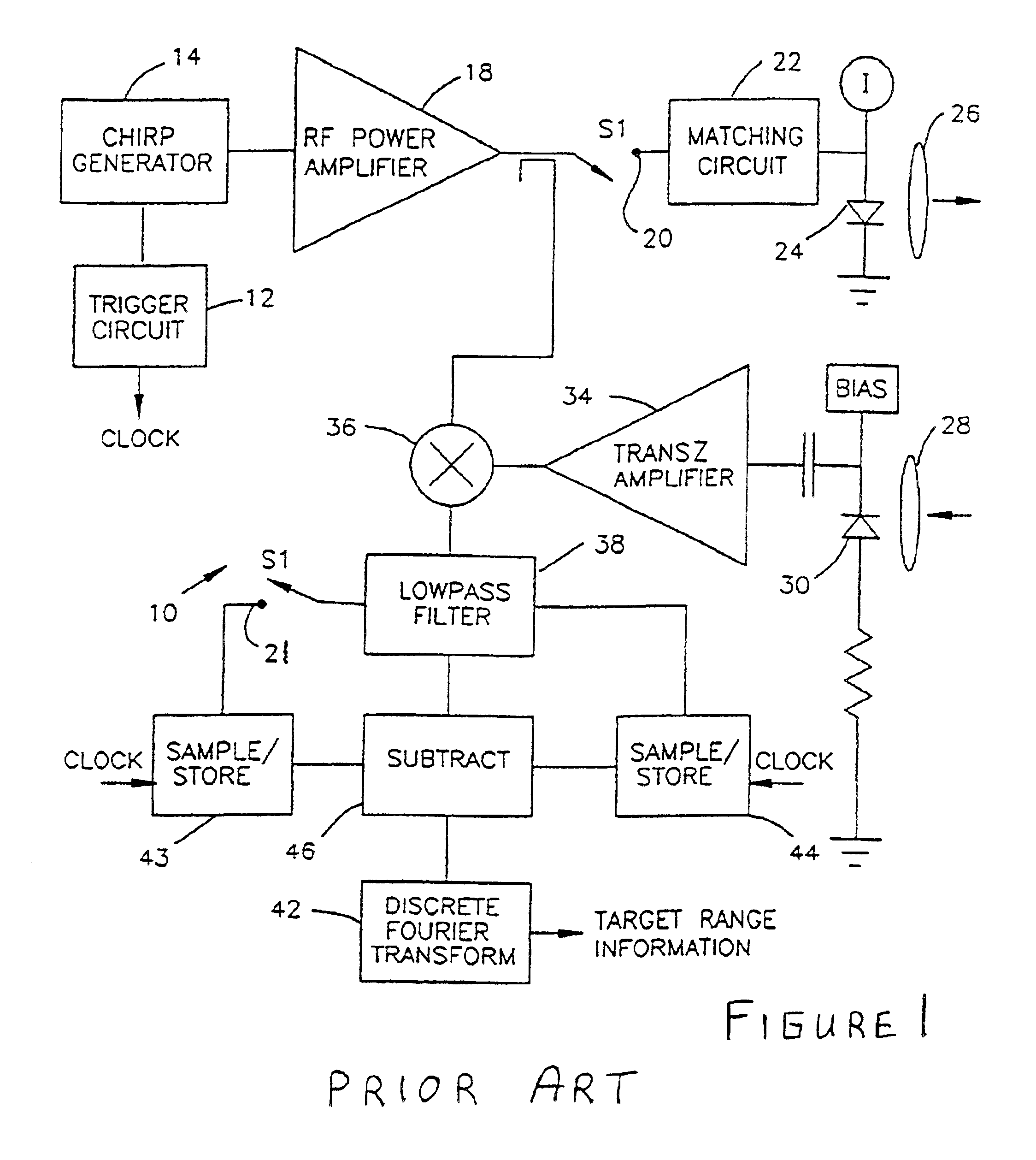
Referring now to FIG. 1 of the drawings, there is generally shown a block diagram of a ladar architecture disclosed in U.S. Pat. No. 5,608,514 ('514 patent). The architecture includes a trigger circuit 12 which activates a chirp generator 14 for producing a signal with a frequency that increases linearly as a function of time over a period of time, T. The chirp signal is fed through a wideband RF power amplifier 18 to a matching circuit 22 that matches the driving impedance of the amplifier to the impedance of a laser diode 24.

Laser diode 24 converts the chirp current waveform into a light waveform with power proportional to the driving current. This divergent laser light beam is collected by a first lens 26, collimated and directed toward a target. The small portion of transmitted light that is reflected by the target and propagated back to the ladar is collected by a second lens 28 and focused onto the active detection region of a photodiode 30. Photodiode 30 converts the collecte...


PUM


Abstract

A high range resolution ladar includes a chirp generator for producing a chirp signal waveform that is used by a laser diode to propagate a divergent laser light waveform. The reflected light signals from the target are directed to a self mixing detector that is coupled to the chirp generator where the responsivity of the detector varies in accordance with the chirp waveform for converting reflected light signals from the target to electrical signals and for mixing the converted electrical signal with the chirp waveform to produce an output electrical signal whose frequency is proportional to the range to the target. The self-mixing detector includes at least one detector having a semiconductor substrate and first and second electrodes deposited on the substrate and spaced from each other, wherein the first set of electrodes is connected to the chirp generator and the second set of electrodes is connected to a memory for storing a plurality of frames of image data.

Description

FIELD OF THE INVENTIONThis invention generally relates to laser detection and ranging (ladar) systems; and more particularly, to an incoherent ladar which achieves high range resolution by employing self-mixing detectors in focal plane detector arrays.BACKGROUND OF THE INVENTIONUse of ladar technologies to form images of targets is set forth in U.S. Pat. Nos. 5,608,514 and 5,877,851 assigned to the same entity, and herein incorporated by reference.Ladar is basically a radar transformed from a system for measuring reflected radio frequency electromagnetic radiation, typically in the 1-25 cm wavelength range to locate remote objects, to a system that operates on laser radiation, typically in the 0.1 to 10.0 μm range. The resulting combination of radar and optics provides a system with inherently enhanced accuracy in the measurement of range, velocity, and angular displacement. Moreover, the high carrier frequency allows ladar systems to be made more compact in physical dimension, whic...

Claims


Application Information

Patent Timeline
IPC IPC(8): G01S17/32G01S17/89G01S17/00G01S7/48G01S7/491G01S17/34G01S17/894
CPCG01S7/491G01S17/89G01S17/325G01S17/34G01S17/894
Inventor RUFF, WILLIAM C.STANN, BARRY L.SHEN, PAUL H.
Owner ARMY US SEC THE
Why Eureka
Try Eureka