
Ion source, method of operating the same, and ion source system

Inactive Publication Date: 2005-01-18
NISSIN ION EQUIP CO LTD
View PDF7 Cites 5 Cited by
  • Summary
  • Abstract
  • Description
  • Claims
  • Application Information

AI Technical Summary

Benefits of technology

Accordingly, an object of the present invention is an ion source which can keep the temperature of a plasma production chamber at the time of plasma production at low temperatures, a method of operating the ion source and an ion source system having the ion source.
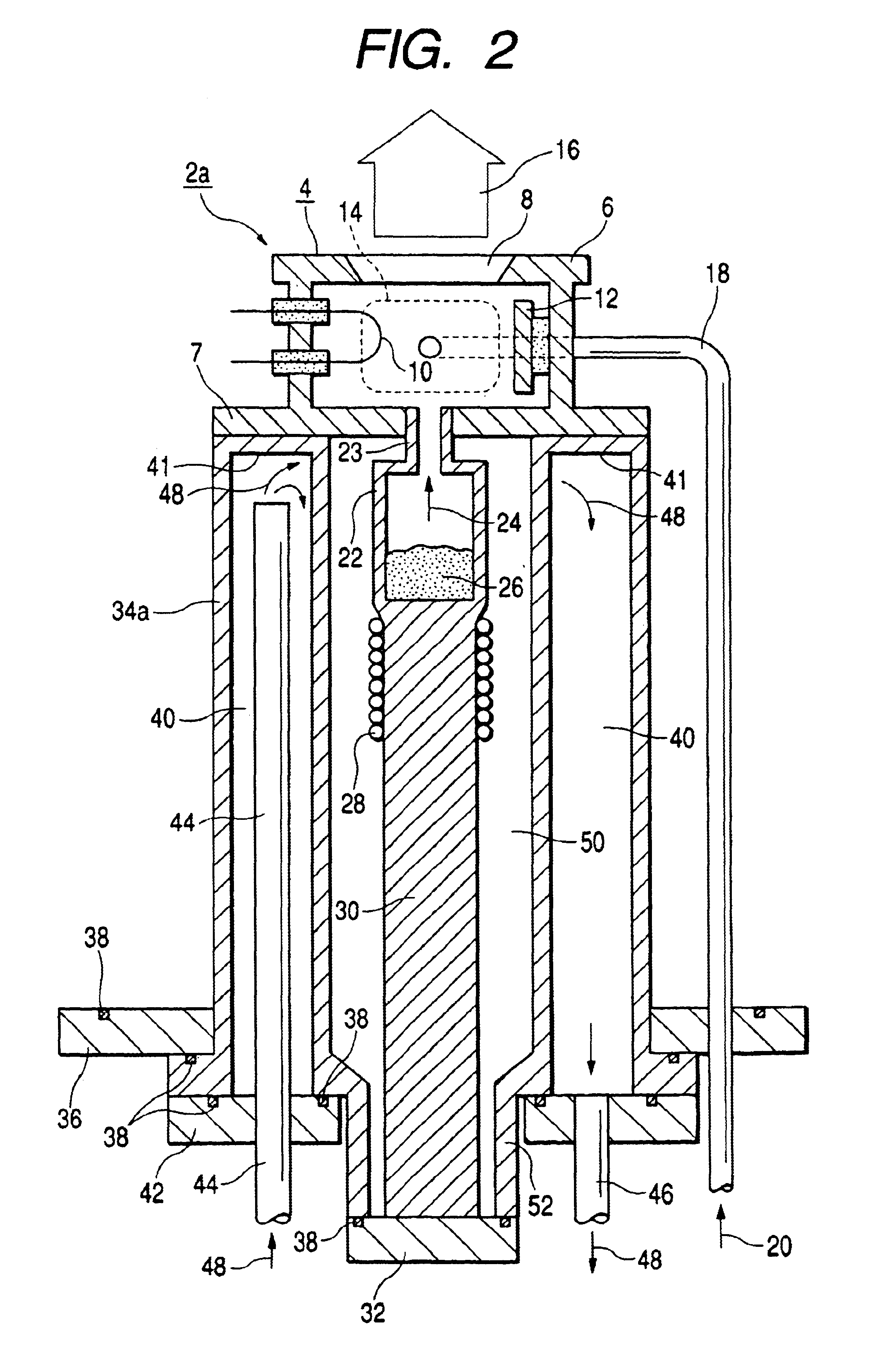
According to the ion source operating method, in the cooling mode, the plasma production chamber is cooled by a cooling medium flowed to the cooling medium passage in the support body. Therefore, the ion source is operated in a state that temperature of the plasma production chamber is relatively low. In the evacuating mode, the thermally insulating effect of the support body is enhanced in a manner that the vacuum-evacuation of the cavity in the support body is carried out and the resulting vacuum insulating operation in the cavity is utilized. Therefore, the ion source is operated in a state that temperature of the plasma production chamber is relatively high. Here, the word “relatively” means “relative to the temperature in the other mode”.
Where the ion source is thus operated selectively in the cooling mode or the evacuating mode, one ion source may be used over a broad range of the temperature of the plasma production chamber. Accordingly, freedom of selecting ion species that may be used is considerably increased.
In the ion source system, the ion source is operable selectively in an operation mode in which the cooling medium is flowed from the cooling medium supplying device to the cavity of the support body (cooling mode), or in another operation mode in which the vacuum-evacuation is carried out for the cavity by the vacuum evacuating device (evacuating mode). One ion source 2a may be used over a broad range of the temperature of the plasma production chamber. Accordingly, freedom of selecting ion species that may be used is considerably increased.

Problems solved by technology

Thus, the decaborane ion beam with a predetermined amount cannot be extracted.
However, it is almost impossible for the related art ion source 2 to achieve such low temperatures of the plasma production chamber 6.

Method used


Image

  • Ion source, method of operating the same, and ion source system
  • Ion source, method of operating the same, and ion source system
  • Ion source, method of operating the same, and ion source system

Examples


first embodiment

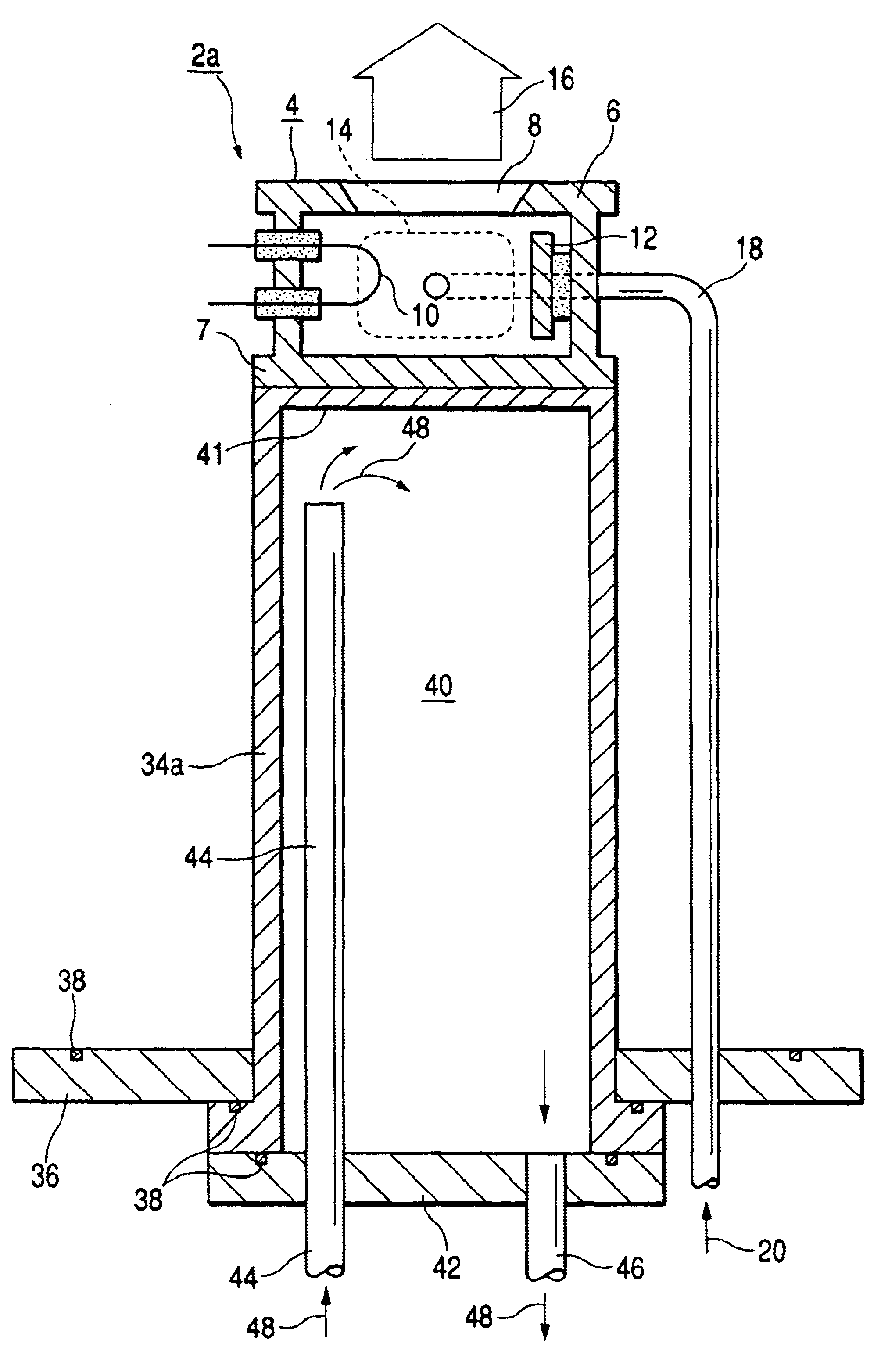
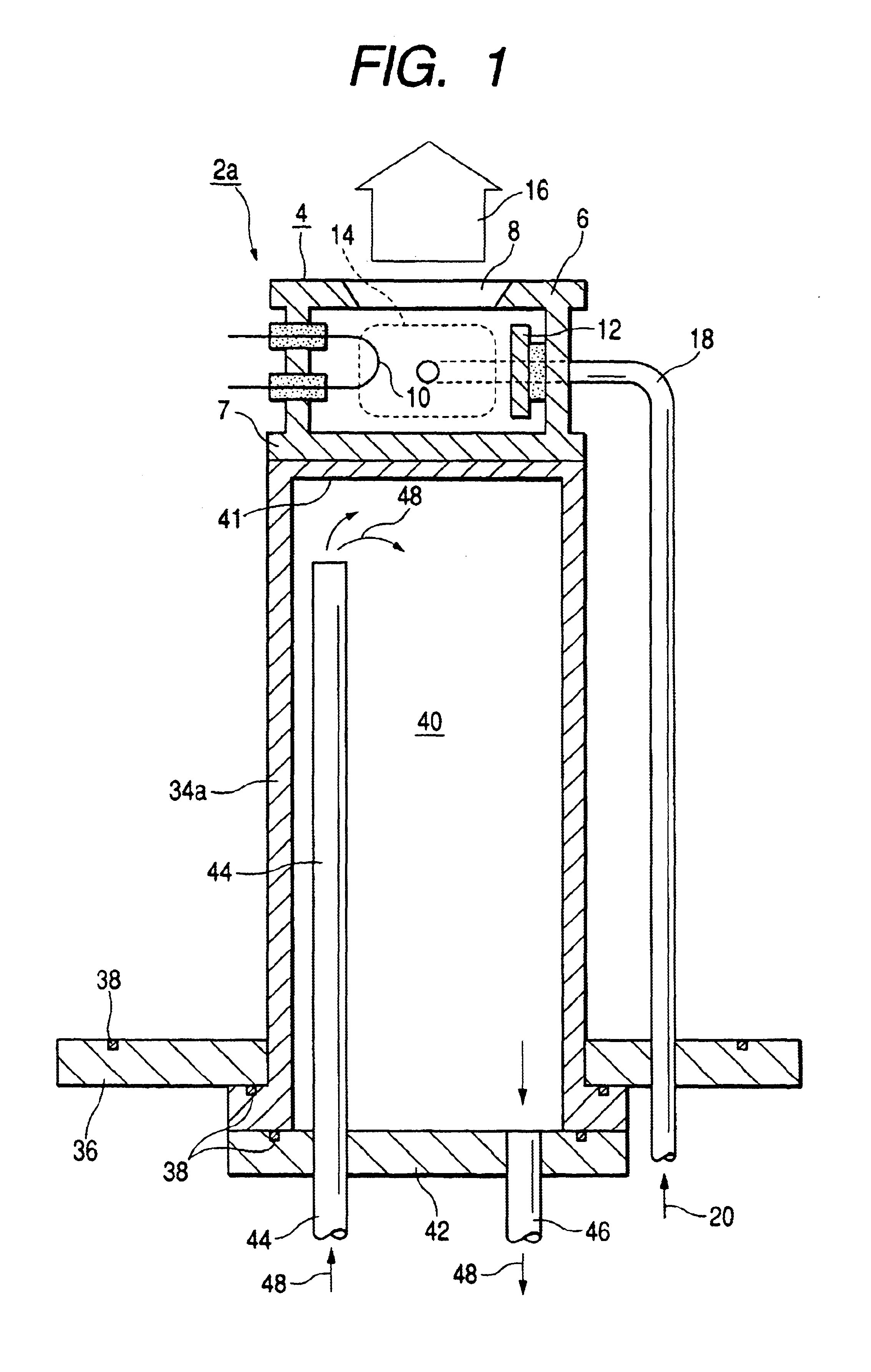
FIG. 1 is a cross sectional view showing an ion source according to the present invention. Like or equivalent portions are designated by like reference numerals used in the related art example shown in FIG. 4, for simplicity. Description will be given placing emphasis mainly on the differences of the ion source from the related art example.

An ion source 2a is equipped with a gas introducing pipe 18, but is not equipped with a vapor generating oven. A support body 34a corresponds to the support members 34 shown in Fog. 4. The support body 34a supports a plasma production chamber 6 of a plasma production section 4 on the basis of an ion source flange 36. Within the support body 34a, a cavity 40 is provided ranging from a position near the plasma production chamber 6 to a position near the ion source flange 36. More specifically, the support body 34a is a tubular body with a bottom surface 41 where the cavity 40 is provided in an interior of the support body 34a. A lid 42 is applied to...


PUM


Abstract

In an ion source, within a support body which supports a plasma production chamber for producing a plasma on the basis of an ion source flange, a cavity is provided ranging from a position near the plasma production chamber to a position near the ion source flange. The cavity serves as a cooling medium passage which introduces a cooling medium to a position near the plasma production chamber to cool the plasma production chamber. The plasma production chamber is cooled at a position very near it by the cooling medium. Therefore, temperature of the plasma production chamber at the time of plasma production is kept at low temperatures.

Description

BACKGROUND OF THE INVENTION1. Field of the InventionThe present invention relates to an ion source which produces a plasma and extracts an ion beam from the produced plasma, a method of operating the ion source and an ion source system having the ion source. More particularly, the present invention relates to means for keeping temperature of a plasma production chamber for producing the plasma at low temperatures at the time of plasma production and means for operating the ion source selectively in a low temperature operation mode and a high temperature operation mode for the plasma production chamber.2. Description of the Related ArtFIG. 4 shows an example of a related art ion source. An ion source 2 comprises a plasma production section 4 which ionizes ion species such as a gas or vapor introduced into the plasma production section 4 to produce a plasma 14. The plasma production section 4 is supported by a plurality (usually 4) of bar-like supporting members (support poles in this...

Claims


Application Information

Patent Timeline
IPC IPC(8): H01J27/20H01J27/04H01J27/02G21K5/04G21K1/00H01J27/08H01J37/08H05H1/24
CPCH01J27/20H01J27/04H01J37/08
Inventor KINOYAMA, TOSHIAKI
Owner NISSIN ION EQUIP CO LTD
Learn More