
Flexible vibratory micro-electromechanical device

a micro-electromechanical device and flexible technology, applied in the field of micro-electromechanical systems, can solve the problems of more susceptibility to signal noise and thicker proof mass

Inactive Publication Date: 2005-01-18
TEMIC AUTOMOTIVE OF NORTH AMERICA
View PDF9 Cites 63 Cited by
  • Summary
  • Abstract
  • Description
  • Claims
  • Application Information

AI Technical Summary

Problems solved by technology

Making the proof masses thicker, however, generates other problems.
For instance, certain frequencies of various vibration modes become undesirable and may become more susceptive to signal noise.

Method used


Image

  • Flexible vibratory micro-electromechanical device
  • Flexible vibratory micro-electromechanical device
  • Flexible vibratory micro-electromechanical device

Examples


Embodiment Construction

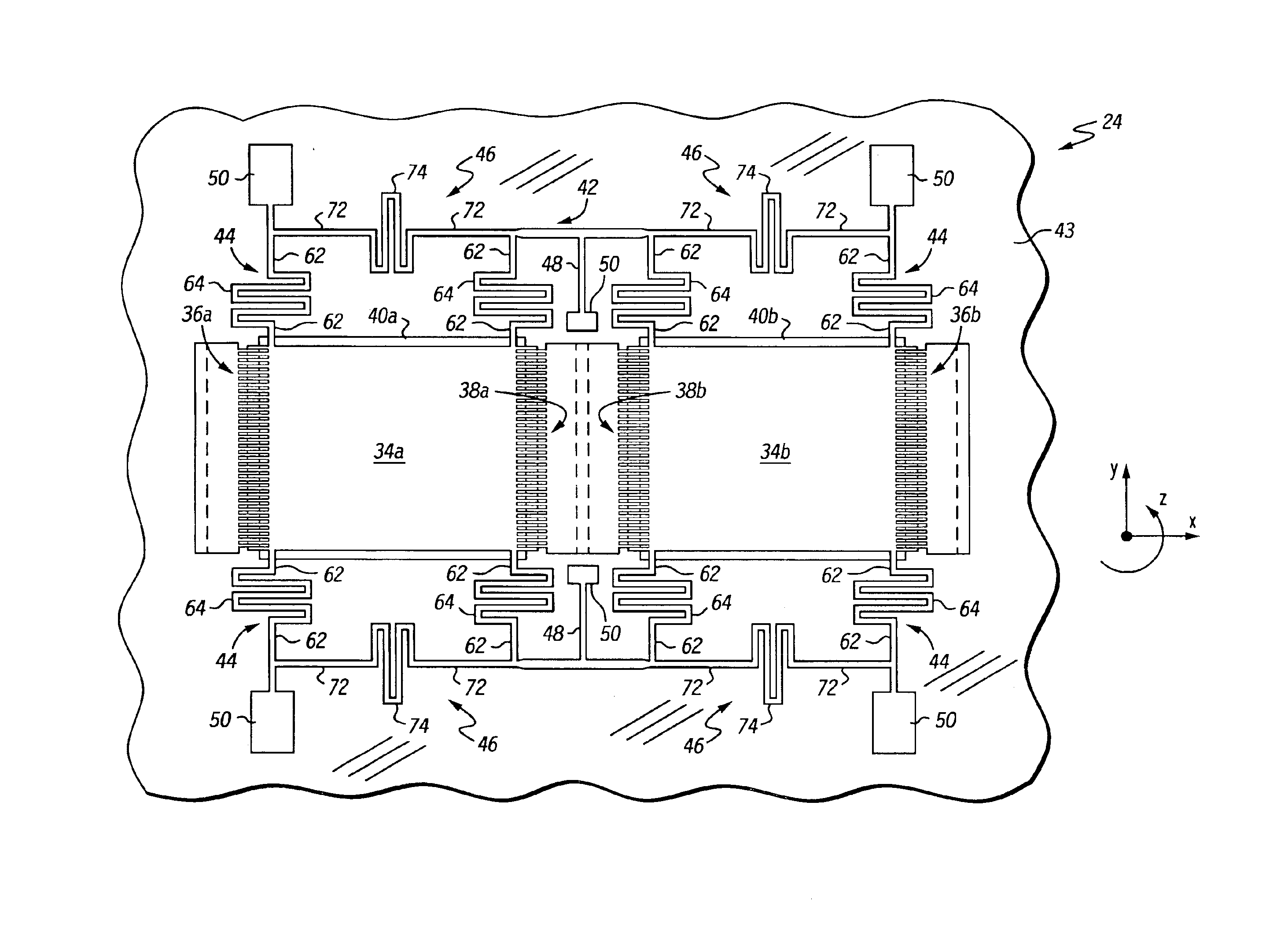
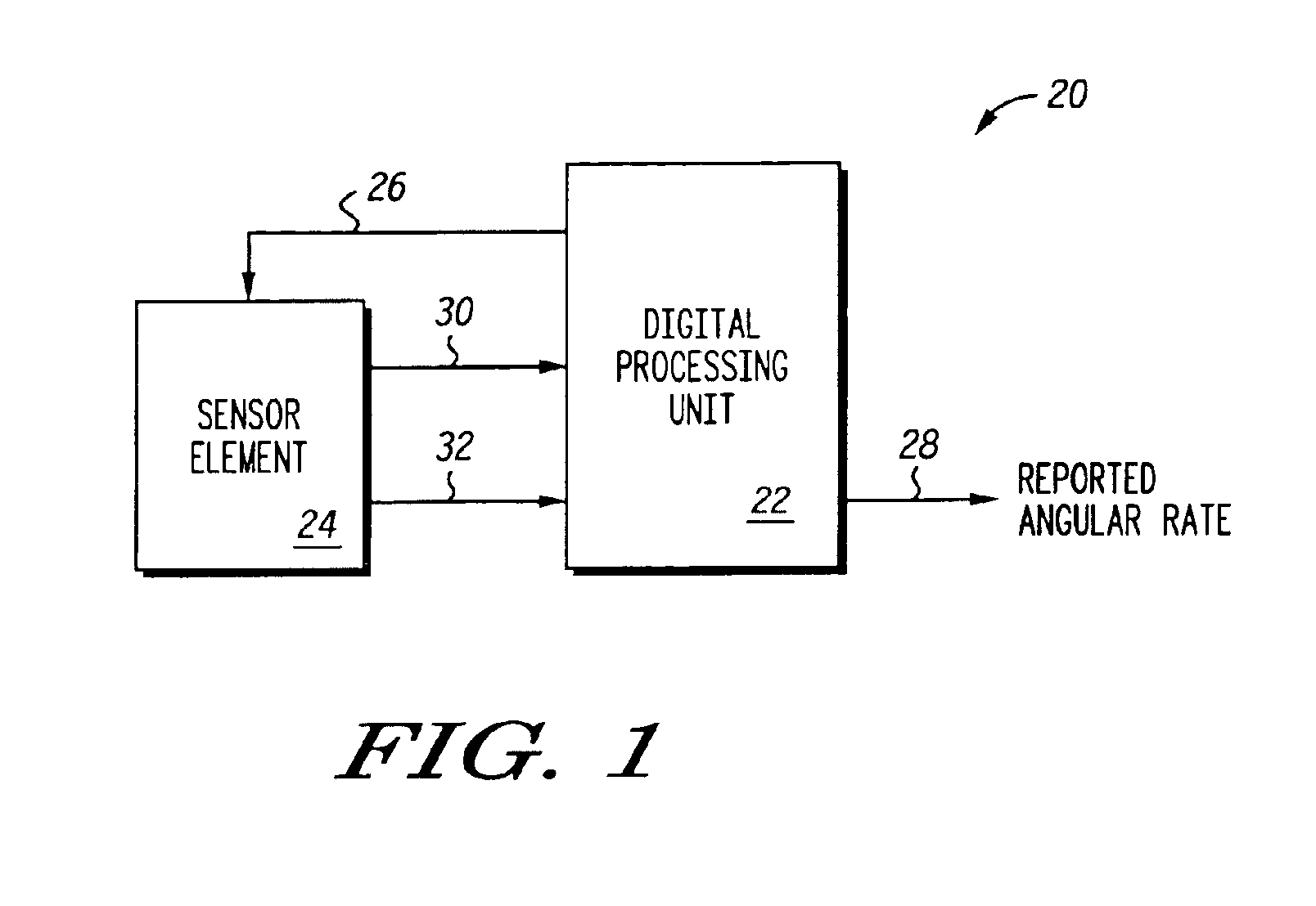
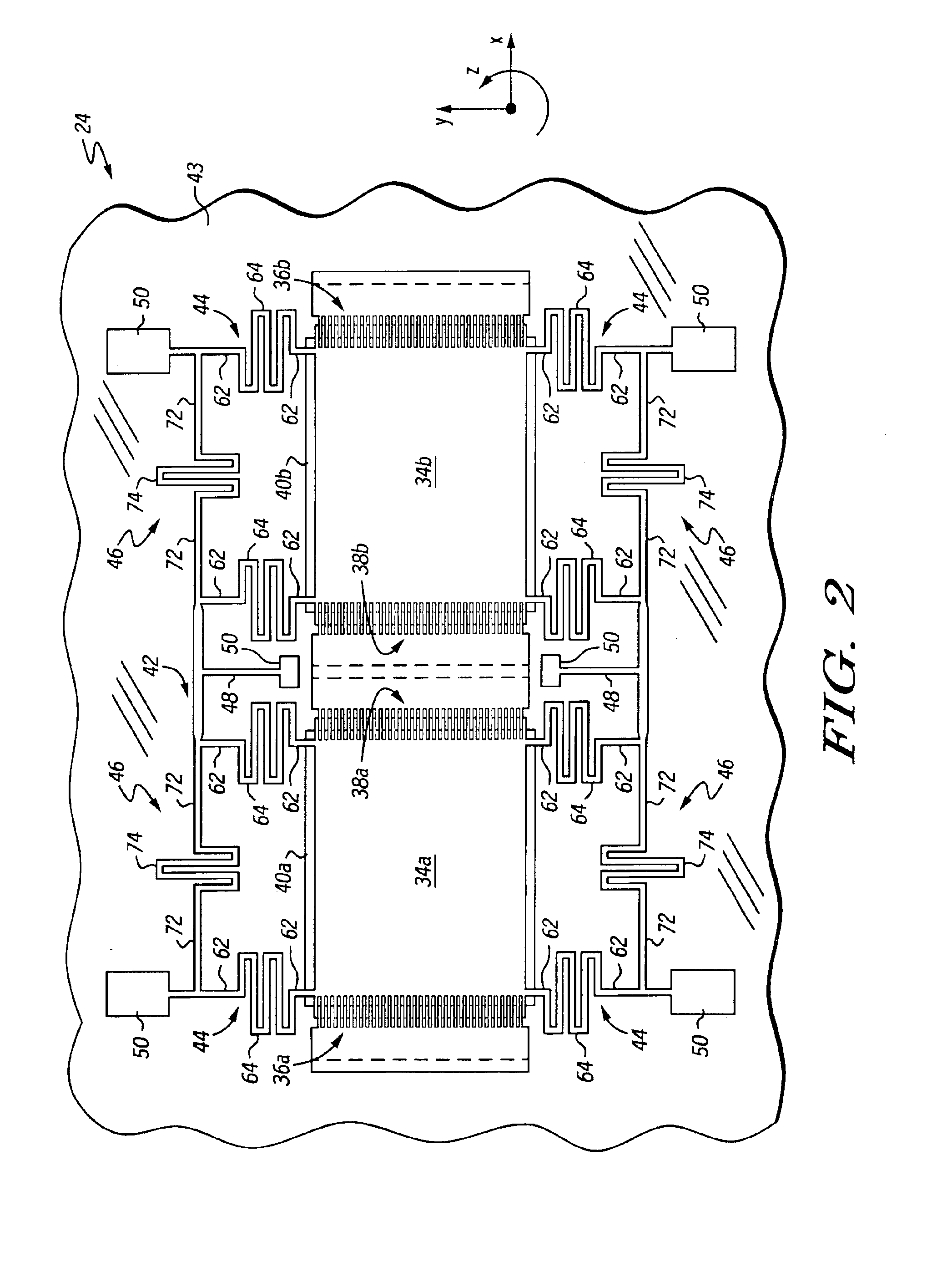
What is described are improved mechanisms and structures in a sensor element of an electronic sensor device that allows for the realignment of relative frequencies at various vibration modes. This allows the sensor device to use thicker movable proof masses, which improves yield in mass production applications and allows process tolerances to be relaxed. To this end, in one embodiment there is a sensor element for a sensor device comprising a substrate, a pair of proof masses, and a set of drive beams. The pair of proof masses is suspended above the substrate and is attached to the substrate at fixed anchor points. The set of drive beams is positioned between the proof masses and the anchor points. The drive beams have a longitudinal body portion that extends along a first direction and a flexible spring member that extends along a second direction. The second direction may be perpendicular to the first direction and the flexible spring members may be serpentine in shape, such as fo...


PUM


Abstract

There is a sensor element (24) for an electronic sensor device (20). The sensor element (24) may have a substrate (43), a pair of proof masses (34a, 34b), a set of drive beams (44), and at least one base beam (46). The pair of proof masses (34a, 34b) are suspended above the substrate (43) and attached to the substrate (43) at fixed anchor points (50). The set of drive beams (44) are positioned between the proof masses (34a, 34b) and the anchor points (50). Each drive beam (44) has a first longitudinal body portion (62) that extends in a first direction and a first flexible spring member (64) that extends along a second direction. The base beam (46) interconnects the set of drive beams (44) and has a second longitudinal body portion (72) and a second flexible spring member (74). The second longitudinal body portion (72) extends along the second direction and the second flexible spring member (74) extends along the first direction. The first and second flexible spring members (64, 74) may be serpentine in shape, such as folded beam-columns or wrinkle springs.

Description

FIELD OF THE INVENTIONThis invention in general relates to micro-electromechanical systems (MEMS) in sensors such as gyroscopes and, more particularly, to the use of flexible vibratory members in the devices.BACKGROUND OF THE INVENTIONElectronic sensor devices manufactured by MEMS technology are playing key roles in many areas. For instance, micro mechanical gyroscopes have enabled several important control systems in transportation and commercial applications. Other microdevices such as pressure sensors, accelerometers, actuators, and resonators fabricated by MEMS technology are also used in many areas.One type of micro gyroscope contains two movable proof masses. The proof masses are suspended above a substrate by a support structure. The proof masses are vibrated in the same plane (in-plane) at a predetermined frequency by a motor in the gyroscope. The motor may include electrodes that drive the proof masses in the same plane in an oscillatory manner. The oscillation of the proof...

Claims


Application Information

Patent Timeline
Patent Type & Authority Patents(United States)
IPC IPC(8): G01P15/08G01C19/00G01P9/00G01P3/44G01P3/42G01P9/04H04N5/225G01B
CPCG01C19/5719
Inventor CHIOU, JEN-HUANG ALBERT
Owner TEMIC AUTOMOTIVE OF NORTH AMERICA
Learn More