
Method and apparatus for assigning frequency channels to a beam in a multi-beam cellular communications system

a multi-beam, cellular communication technology, applied in the field of cellular communication, can solve the problems of omnidirectional cell antennae with relatively low call capacity, overly susceptible to interference, and limited number of frequency channels available on any given cell, so as to reduce the likelihood of muting or blocking the call, and reduce the occurrence of muting.

Inactive Publication Date: 2005-01-11
MICROSOFT TECH LICENSING LLC
View PDF15 Cites 57 Cited by
  • Summary
  • Abstract
  • Description
  • Claims
  • Application Information

AI Technical Summary

Benefits of technology

In this manner, conflicting channel demands may be intelligently resolved, by balancing channel quality and traffic demands. Priority values may be dynamically calculated so as to assign a higher priority value to a particular channel for a given beam when traffic demand in that beam is high, effectively defining such a channel as a “preferred” channel for that beam. Conversely, the priority value may be reduced as traffic demand in the beam decreases, thereby making it more likely that the channel will be assigned to a different beam if needed.
Specific embodiments of this latter aspect of the invention will allow a wireless telecommunication service provider to reduce the occurrence of “muting” and of blocking or loss of calls as a user of a wireless telecommunications device such as a cellular telephone moves from one region to another adjacent region. The service provider will be able to intelligently decide, on the basis of channel quality, whether it is feasible to simply transfer the call, on the same frequency channel, to the adjacent region, thereby eliminating the need for the cellular telephone to re-tune to a new frequency, which in turn reduces the likelihood of muting or blocking of the call. Conventional re-tuning will occur only if the channel quality of the current frequency channel would not be adequate in the adjacent region to permit the call to continue to be conducted on the same frequency.

Problems solved by technology

However, omnidirectional cell antennae typically have relatively low call capacities, and are overly susceptible to interference, as interference on a given frequency channel will prevent use of that channel anywhere within the cell, even if the interference is actually affecting only a relatively narrow angular region within the cell.
It will be appreciated that the number of frequency channels available on any given cell is limited, due to the allocated spectrum for cellular communications and due to interference requirements which prevent a given cell from using the same set of frequencies as an adjacent cell.
However, existing channel allocation methods do not appear to be suitable for multi-beam systems.
However, FCA fails to account for the dynamic nature of signal traffic or traffic demand within the cell.
For example, at a given instant, only half of the available channels at the cell might be in use, but a particular user might not be able to place a call, simply because the user happened to be physically located within a beam in which all eight pre-allocated channels were in use, even though an adjacent beam might have none of its channels in use.
Further, if the number of beams is increased, the number of fixed channels allocated per beam decreases, thus decreasing the trunking efficiency.
In other words, the same frequency channels which are clear in one beam often tend to be equally clear in an adjacent beam, and the channels which are noisy in one beam are often equally noisy in the adjacent beam.
Thus, in a multi-beam system, channel quality alone is not sufficient to resolve competing demands from adjacent beams for a new frequency channel.
Although such a hand-off ideally occurs sufficiently quickly that it is not noticeable to the user, occasionally a brief “mute” or signal interruption will occur, or the call may even be blocked or lost.
This difficulty is aggravated in a multi-beam system, in which the regions (beams) are smaller, with the result that a larger number of hand-offs are required to track the user of the wireless communications device over a given range of movement.

Method used


Image

  • Method and apparatus for assigning frequency channels to a beam in a multi-beam cellular communications system
  • Method and apparatus for assigning frequency channels to a beam in a multi-beam cellular communications system
  • Method and apparatus for assigning frequency channels to a beam in a multi-beam cellular communications system

Examples


Embodiment Construction

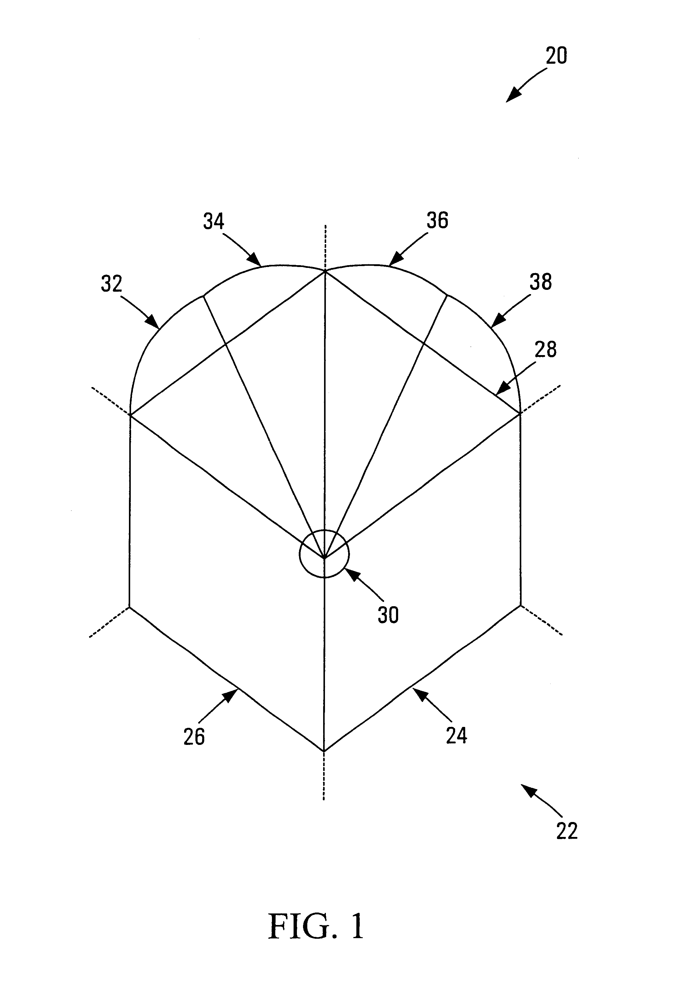
As shown in FIG. 1, a system for assigning frequency channels to a beam in a multi-beam cellular communications system is designated generally by the reference character 20. A geographic region in which wireless communication service is to be provided is divided into a plurality of adjacent hexagonally shaped cells, one of which is shown at 22. In this embodiment, each cell is approximately thirty square kilometers, although it will be appreciated that cells of alternative sizes may be employed.

Each cell is further subdivided into a plurality of sectors. In this embodiment, the cell 22 is subdivided into three 120° sectors 24, 26 and 28, although alternatively the cell may be divided into a different desired number of sectors.

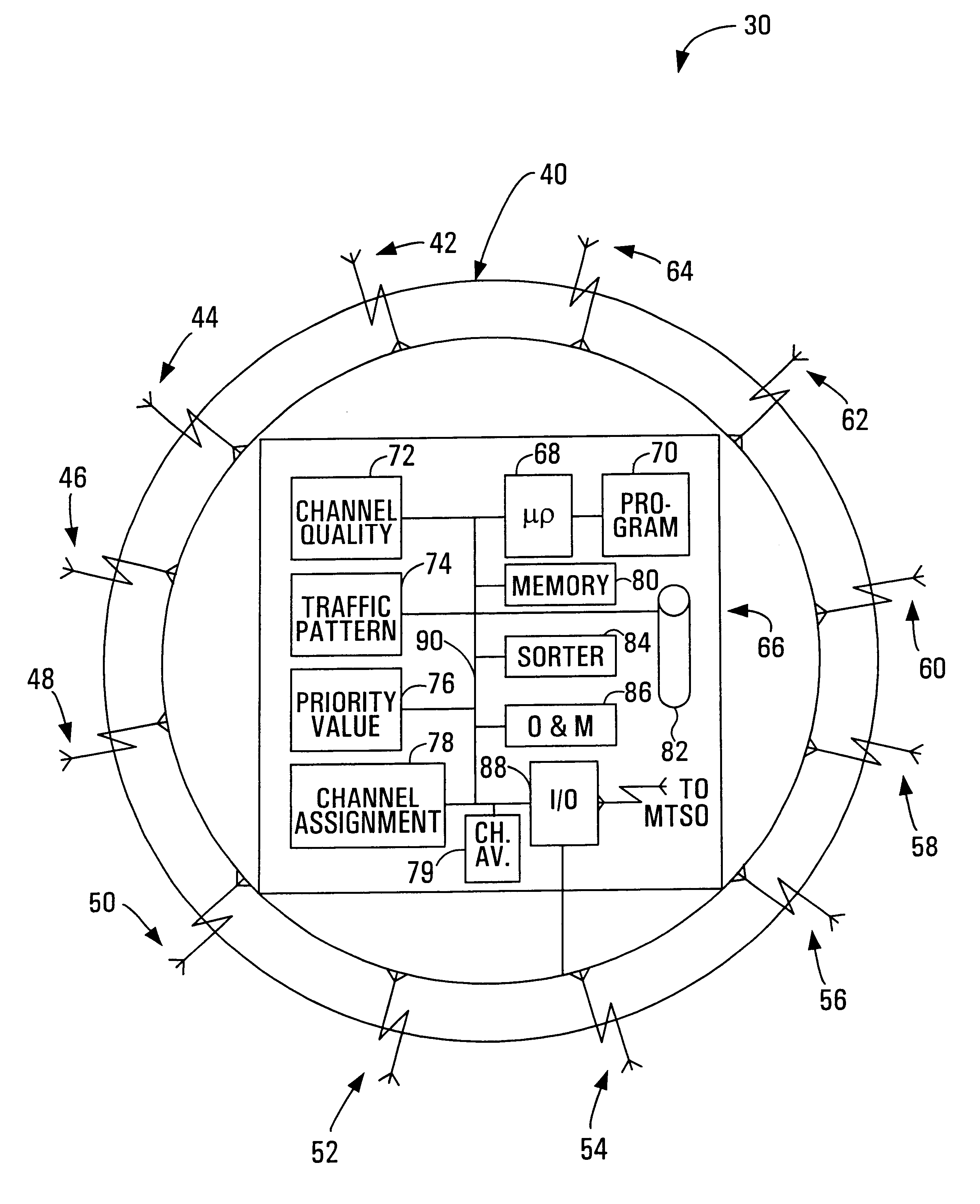
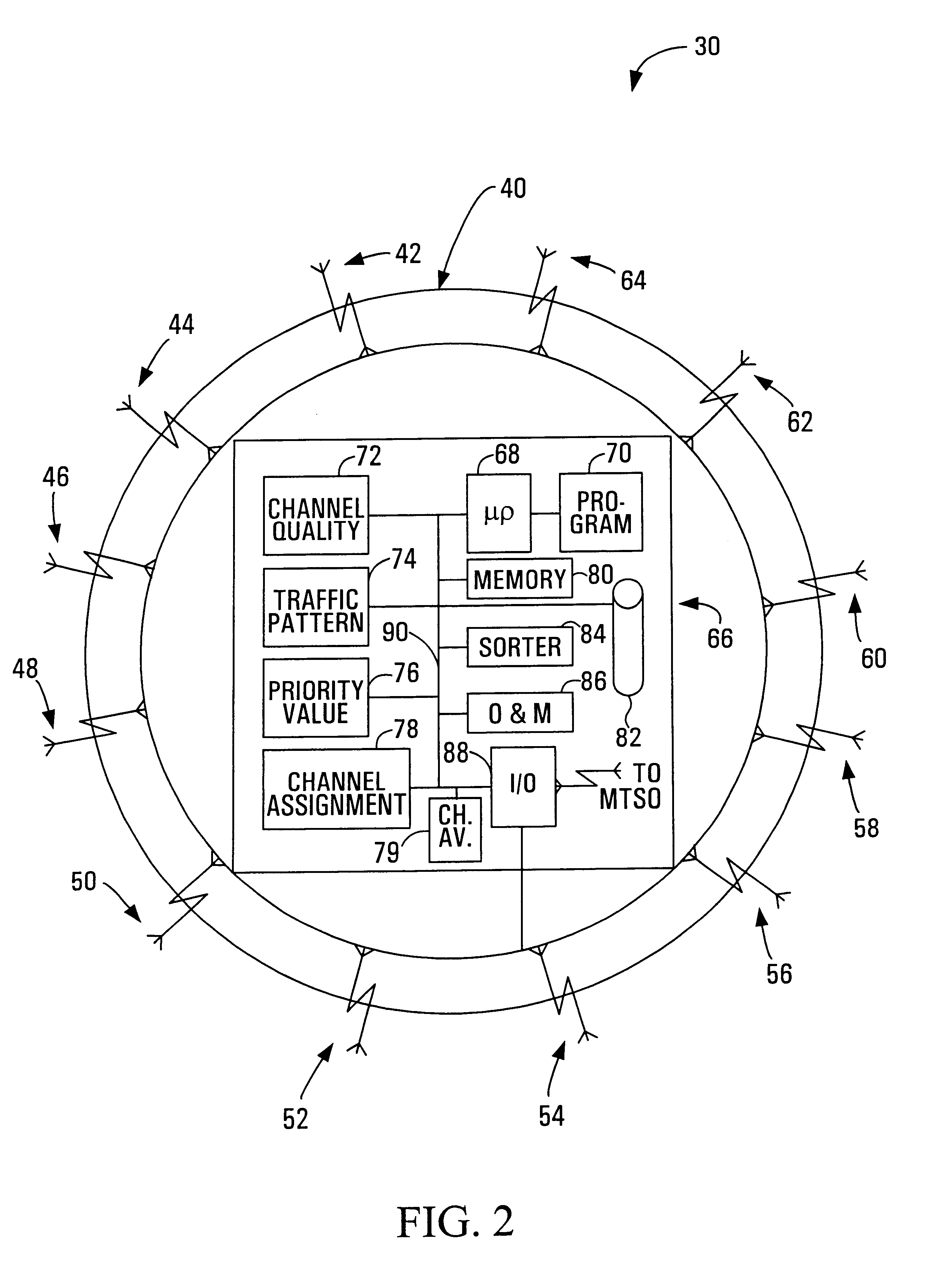
A base station shown generally at 30 is located at the center of the cell 22. Generally, the base station serves as a central transmitter / receiver within the cell for effecting wireless communications with cellular communications subscribers who are presently...


PUM


Abstract

Methods, apparatus, media and signals for assigning frequency channels to a beam in a multi-beam cellular communications system are disclosed. One method involves receiving an indication of channel quality representing a channel quality in the second region, of a frequency channel used in the first region to communicate with the source. The method further involves handing off the frequency channel to a transceiver in the second region to cause the transceiver in the second region to use the frequency channel to communicate with the source in the second region, in response to the indication representing at least a pre-determined minimum channel quality.

Description

FIELD OF THE INVENTIONThe present invention relates to cellular communications, and more particularly to methods and apparatus for assigning frequency channels to a beam in a multi-beam cellular communications system, and for communicating with a source moving from a first region to a second region.BACKGROUND OF THE INVENTIONIn recent years, the popularity of wireless communication devices, such as cellular telephones for example, has increased exponentially, to the point where such devices are practically household items.Providers of wireless telecommunication services typically divide a geographic region into a plurality of adjacent hexagonally-shaped “cells”, each cell having a central base station for transmitting and receiving to and from any wireless communication devices which are presently located within the cell. Many older base stations include omnidirectional transceivers for transmitting and receiving in all directions within the cell. However, omnidirectional cell anten...

Claims


Application Information

Patent Timeline
Patent Type & Authority Patents(United States)
IPC IPC(8): H04Q7/36H04W16/28
CPCH04W16/28H04W28/16H04W28/08
Inventor PERIYALWAR, SHALINI SURESH
Owner MICROSOFT TECH LICENSING LLC
Learn More