Current-mode circuit for implementing the minimum function

a current-mode circuit and function technology, applied in the field of circuits, can solve the problems of large op-amps, inability to interfacing with current-mode circuitry, and inability to add resistors,

Inactive Publication Date: 2005-01-11
TEXAS INSTR INC
View PDF4 Cites 2 Cited by
  • Summary
  • Abstract
  • Description
  • Claims
  • Application Information

AI Technical Summary

Problems solved by technology

This has the disadvantage of not interfacing to current-mode circuitry, such as Gilbert translinear circuits, without the addition of resistors.
The op-amps are large, and consume significant amounts of current.

Method used


Image

  • Current-mode circuit for implementing the minimum function
  • Current-mode circuit for implementing the minimum function
  • Current-mode circuit for implementing the minimum function

Examples


Embodiment Construction

The numerous innovative teachings of the present invention will be described with particular reference to an exemplary embodiment. However, it should be understood that this exemplary embodiment-provides only one example of the many advantageous uses and innovative teachings herein. In general, statements made in the specification of the present application do not necessarily delimit any of the various claimed inventions. Moreover, some statements may apply to some inventive features, but not to others. Throughout the drawings, it is noted that the same reference numerals or letters will be used to designate like or equivalent elements having the same function. Detailed descriptions of known functions and constructions unnecessarily obscuring the subject matter of the present invention have been omitted for clarity.

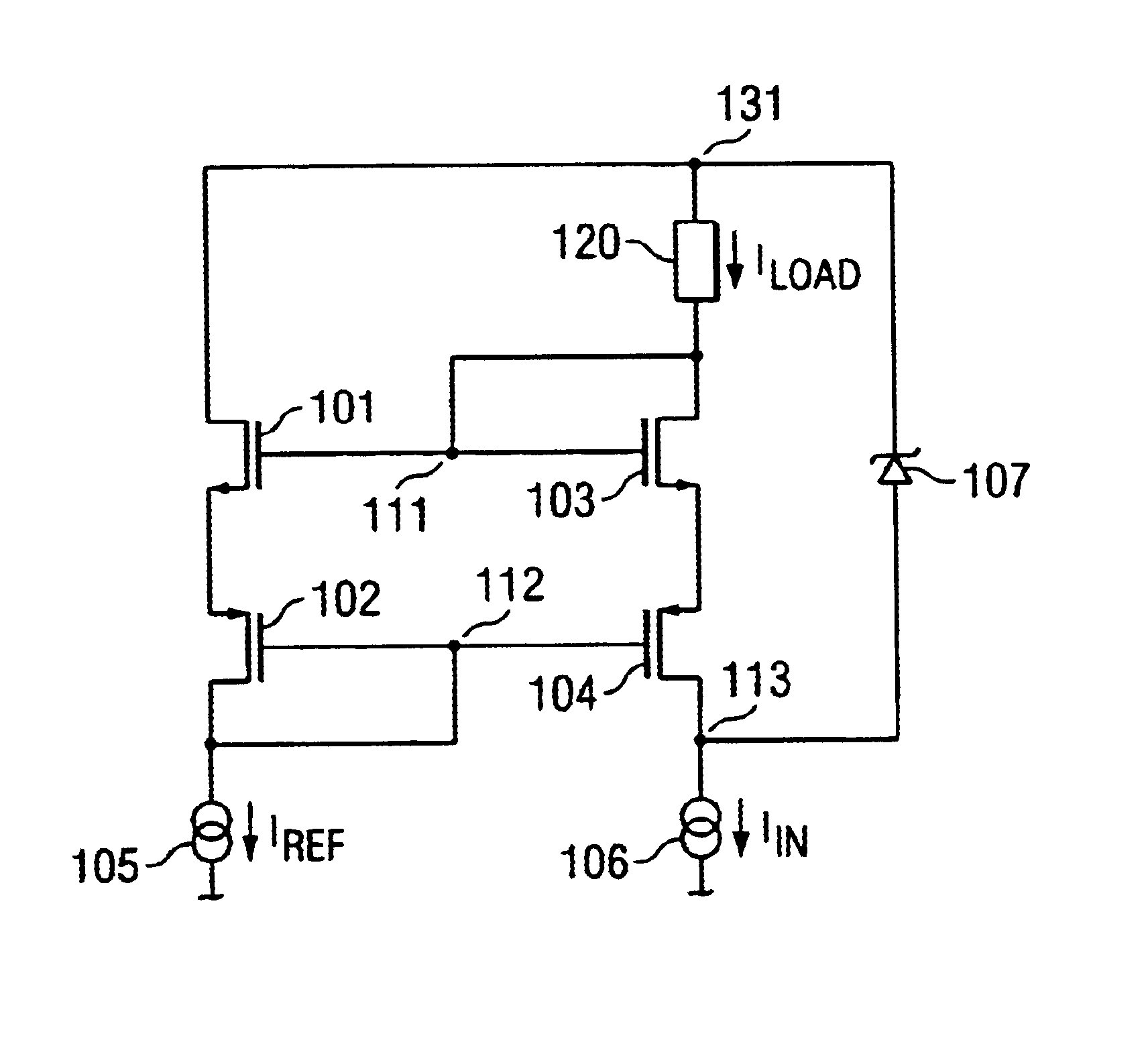
FIG. 2 illustrates an exemplary embodiment of the present invention. Assuming the dimensions of transistors 101 and 103 are equal, and likewise the dimensions of transist...


PUM


Abstract

The present invention comprises a circuit consisting of four transistors (101-104) and an optional clamping Zener (107) arranged such that the current drawn through a load (120) is equal to the lesser of an input current (106) and a reference current (105).

Description

FIELD OF THE INVENTIONThe present invention relates to circuits designed to provide an output signal proportional to a function of a plurality of inputs. More specifically, it relates to a circuit whose output current is proportional to the lesser of two input currents.BACKGROUND OF THE INVENTIONThere are a number of circuits and techniques for implementing minimum and maximum functions. One example, as seen in FIG. 1, uses a pair of operational amplifiers OA1, and OA2. As seen therein, the circuit receives input signals X1 and X2, both in the form of voltages, and produces output signal Y, a voltage that satisfies the function:Y=min(X1, X2) This prior art circuit uses voltages rather than currents as its signals. This has the disadvantage of not interfacing to current-mode circuitry, such as Gilbert translinear circuits, without the addition of resistors. The op-amps are large, and consume significant amounts of current. The present invention comprises an improved circuit to implem...

Claims


Application Information

Patent Timeline
Patent Type & Authority Patents(United States)
IPC IPC(8): G05F3/08G05F3/26
CPCG05F3/262
Inventor HASTINGS, ROY ALANTHOMPSON, II, LEMUEL HERBERT
Owner TEXAS INSTR INC
Why Eureka
Try Eureka