Method and system for selecting data sampling phase for self timed interface logic

a data sampling and interface logic technology, applied in the field of methods and apparatus for transmitting data, can solve the problems of slightly too late or too early selection of taps

Inactive Publication Date: 2005-01-04
IBM CORP
View PDF20 Cites 39 Cited by
  • Summary
  • Abstract
  • Description
  • Claims
  • Application Information

AI Technical Summary

Problems solved by technology

In the current implementation of STI a round-off error may occur that causes the selected tap to be taken slightly too late or slightly too early relative to the mid-point of the data window.

Method used


Image

  • Method and system for selecting data sampling phase for self timed interface logic
  • Method and system for selecting data sampling phase for self timed interface logic
  • Method and system for selecting data sampling phase for self timed interface logic

Examples


Embodiment Construction

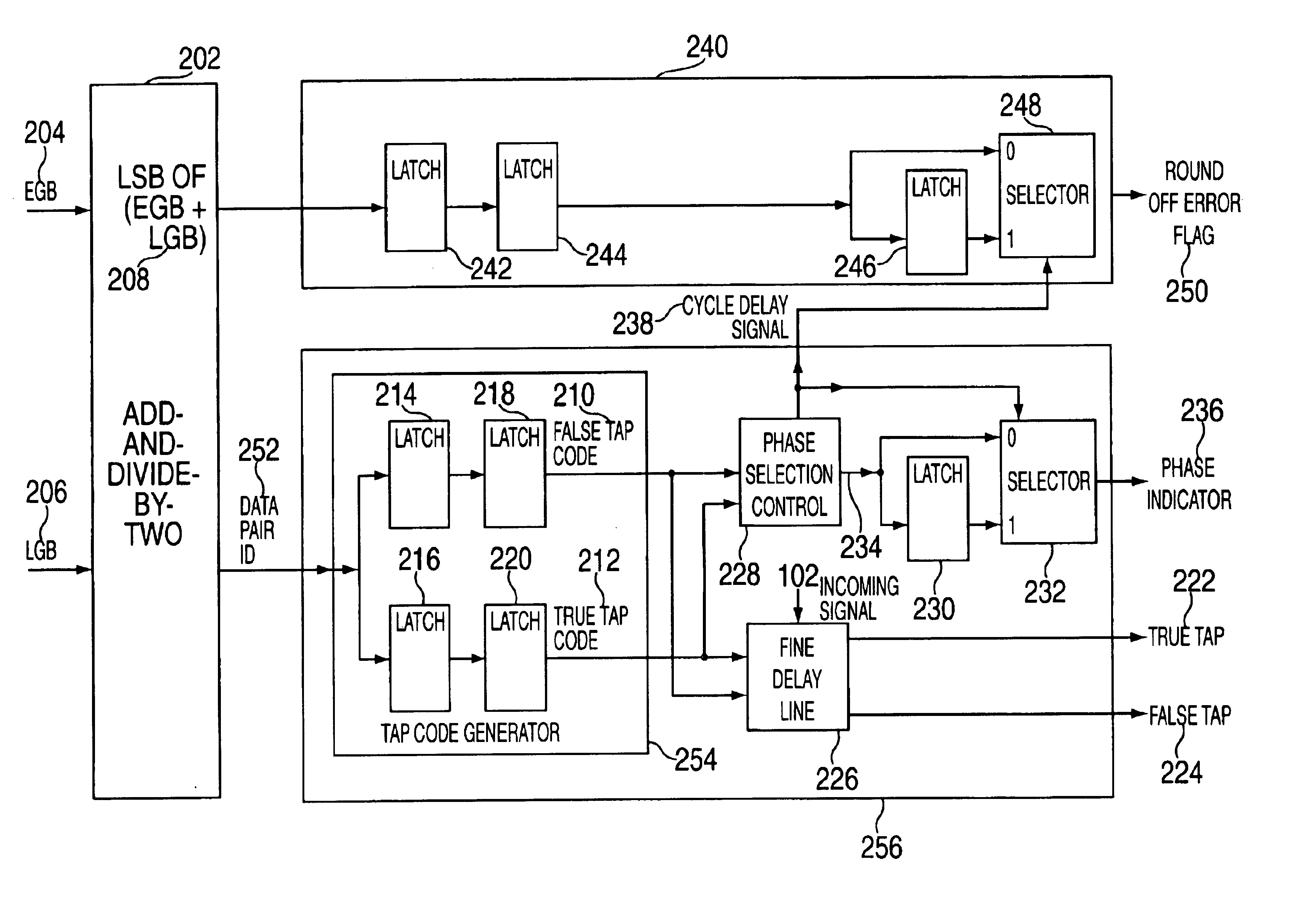
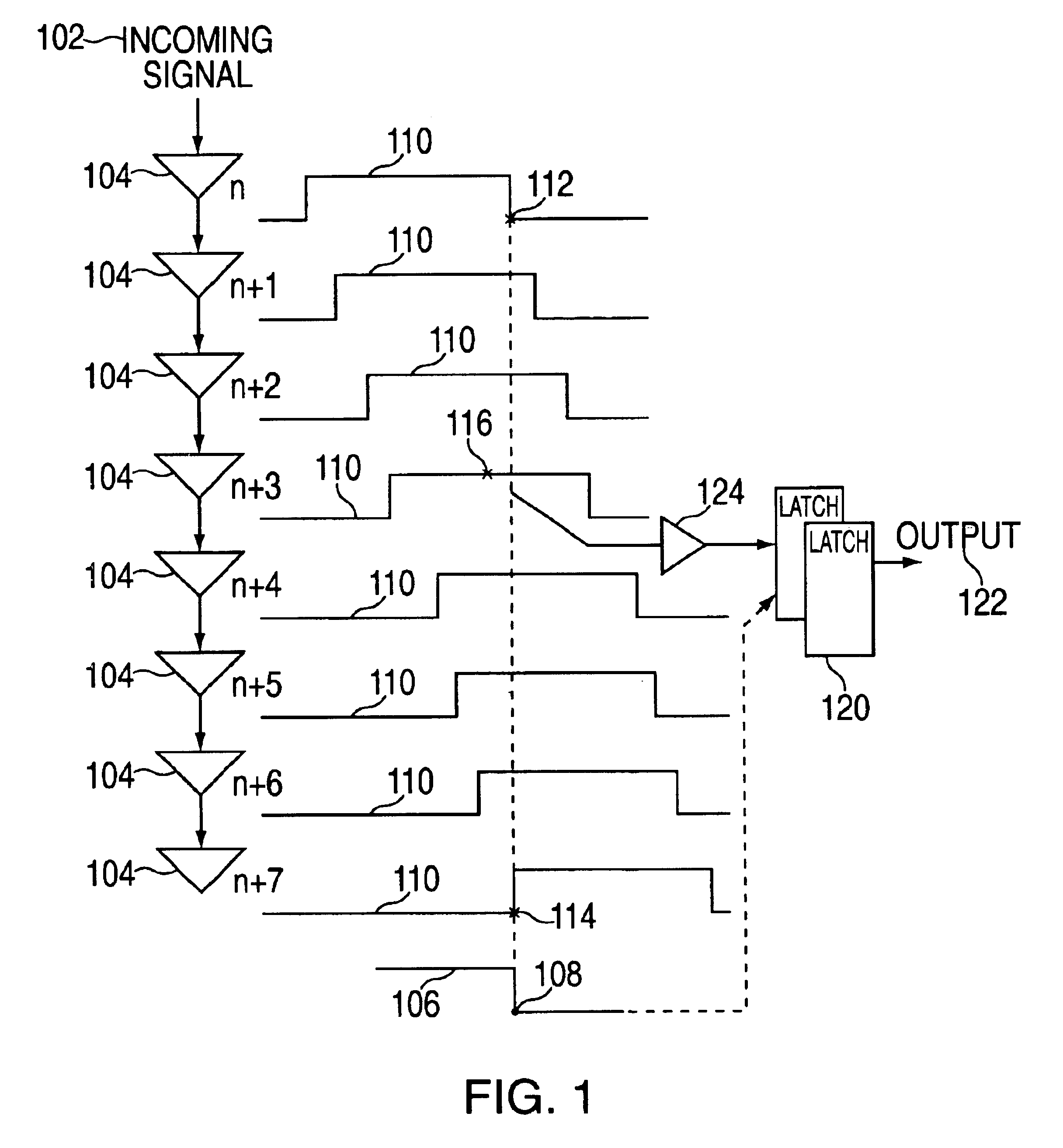
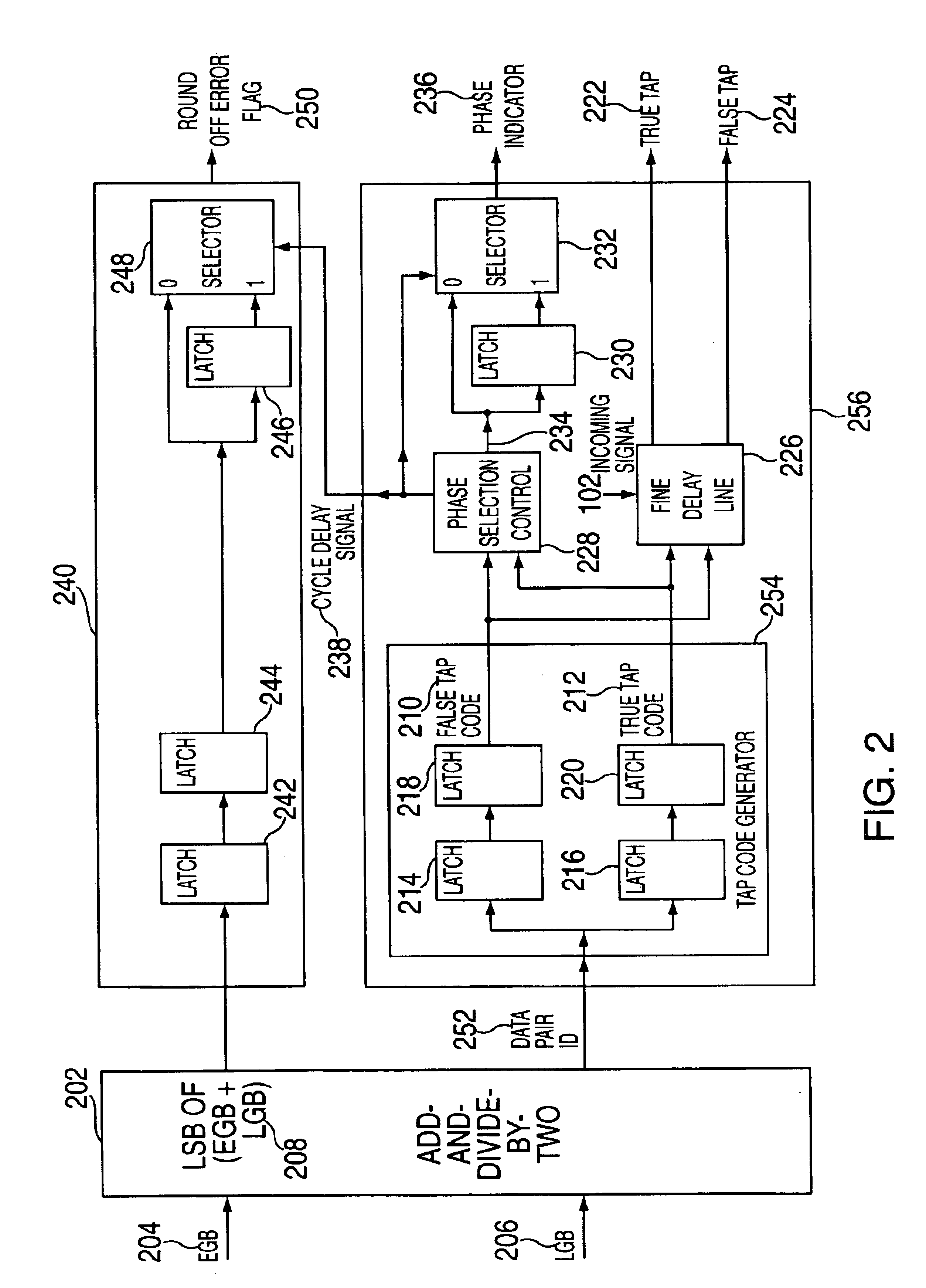
The present invention discloses a method to detect and then to reduce or remove the round-off error that may occur when the self-timed interface (STI) logic selects one of the incoming signal phases. FIG. 1 is an overview of how an exemplary embodiment of the present invention fits into a sample STI delay chain architecture at the receiver microprocessor. According to an embodiment of the present invention, a half-delay 124 is inserted into the delay chain in order to improve the accuracy of the data sampling. The rest of FIG. 1 depicts an example STI delay chain architecture as is known in the art. Each incoming signal 102 in the receiver multiprocessor is sent to a delay line with multiple delay elements 104. The output of each delay element 104 represents a phase of the incoming signal 102. In this manner a large number of phases 110 are generated with progressively increasing offsets. The optimum time to sample the data is when the sampling edge 108 of the clock 106 is aligned w...


PUM


Abstract

An exemplary embodiment of the present invention is a method for transmitting data among processors over a plurality of parallel data lines and a clock signal line. A receiver processor receives both data and a clock signal from a sender processor. At the receiver processor a bit of the data is phased aligned with the transmitted clock signal. The phase aligning includes selecting a data phase from a plurality of data phases in a delay chain and then adjusting the selected data phase to compensate for a round-off error. Additional embodiments include a system and storage medium for transmitting data among processors over a plurality of parallel data lines and a clock signal line.

Description

FIELD OF THE INVENTIONThe present invention relates generally to an improved method and apparatus for transmitting data at high speeds via a parallel data bus, and more particularly to an improvement in the accuracy of selecting the data sampling phase for self-timed interface logic.BACKGROUND OF THE INVENTIONIn many instances data must be transferred between multiple computer components or computer nodes. An example is data transfer between two microprocessors. One way to perform the data transfer is to have a set of latches in the sender microprocessor launch the data through a set of off-processor drivers and into a set of cables. The receiver microprocessor could interface to these cables through a set of off-processor receivers that first amplify the respective signals and then load them into a set of receiving latches which are strobed by a clock sent from the sender microprocessor. With this arrangement, the receiver clock and the sender clock maintain a fixed relationship in...

Claims


Application Information

Patent Timeline
IPC IPC(8): H04L7/033H04L25/14H04L7/00
CPCH04L25/14H04L7/0338H04L7/0008
Inventor HOKE, JOSEPH MICHAELFERRAIOLO, FRANK D.LO, TIN-CHEEYAROLIN, JOHN MICHAEL
Owner IBM CORP
Why Eureka
Try Eureka