
Multi-period cycle-alternative switching mode power supply control device

a power supply control and multi-period cycle technology, applied in the direction of electric variable regulation, process and machine control, instruments, etc., can solve the problems of affecting the reliability of the whole system, affecting the control range of the control device, and the element producing audible noise, etc., to achieve the effect of excitating the loading terminal, improving the control range of the regulation control, and suppressing audible nois

Inactive Publication Date: 2005-01-04
SHIN JIUH +1
View PDF10 Cites 9 Cited by
  • Summary
  • Abstract
  • Description
  • Claims
  • Application Information

AI Technical Summary

Benefits of technology

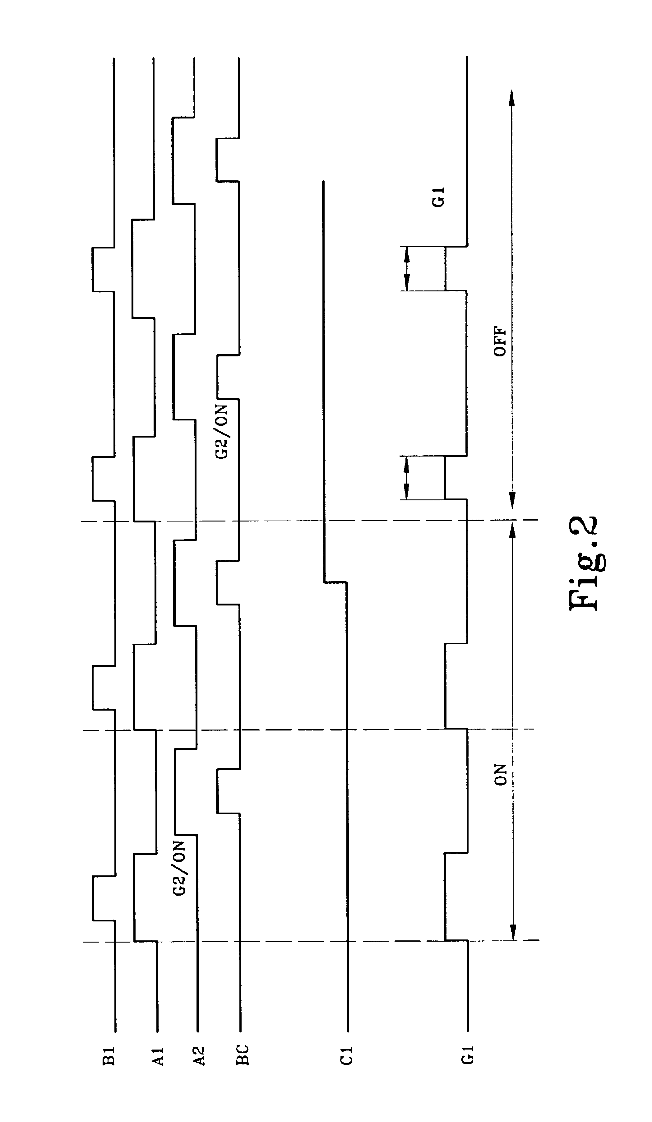
The primary objective of the present invention is to overcome the shortcomings and avoid the deficiencies of the prior art by providing a standby mode function during the off cycle, which greatly improves the regulation control range of the original system, and maintains an overall action of the power transfer element. Therefore the audible noise can be suppressed. Each of the ON and OFF cycles provides different power transfer, and also effectively excites the loading terminal, so that the system performance of the power transfer element and the device at the loading terminal can be controlled effectively, and thus making the product more reliable and efficient.
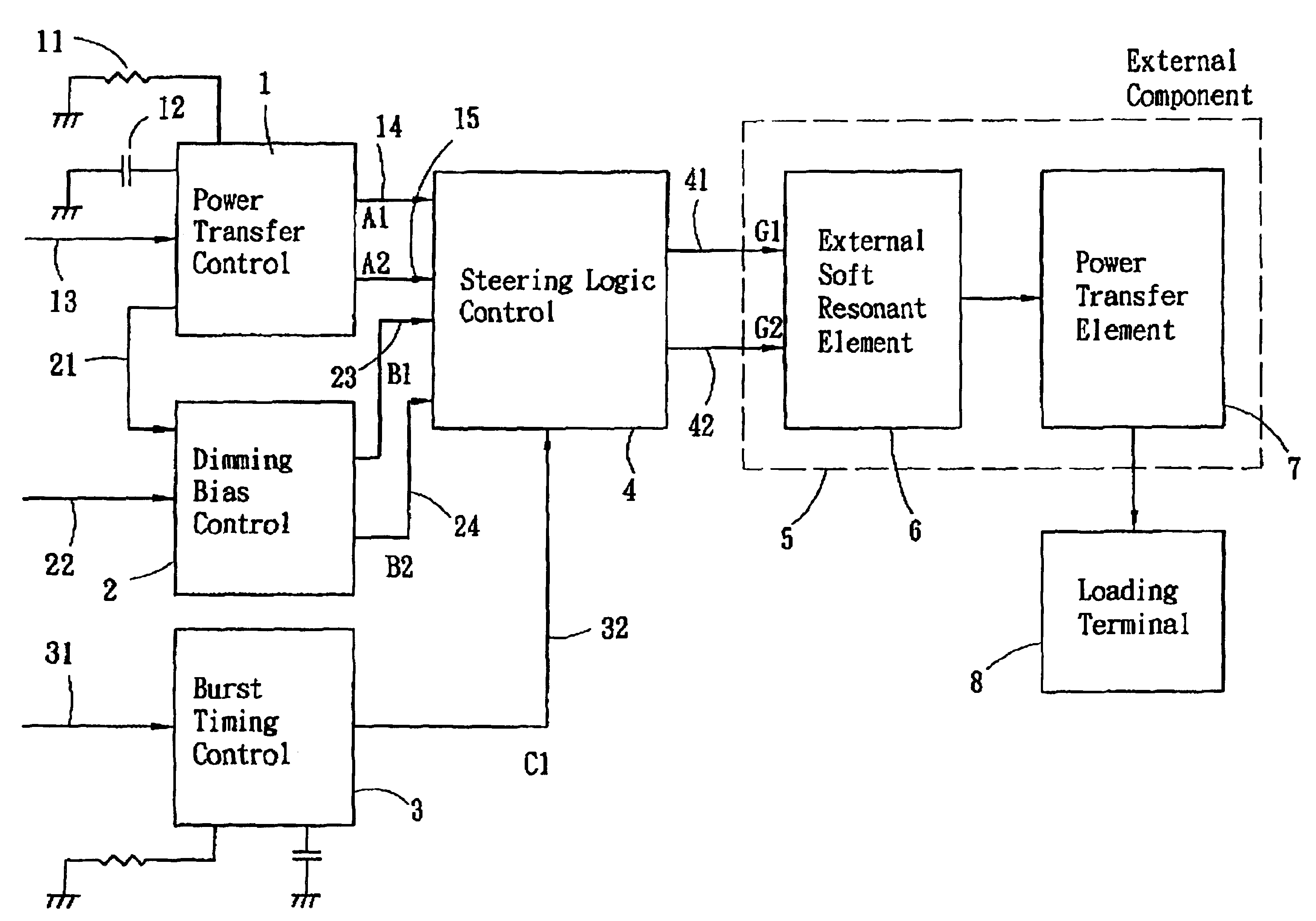
To accomplish the aforementioned purpose, the multi-period alternative-cycle switching power supply control device of the present invention comprises a power transfer control, a dimming bias control, a burst timing control, and a steering logic; wherein said device has a variable multi-period control cycle to effectively control certain power transfer elements of specific nature and assure those elements and the loading at the rear end can operate more efficiently in a reliable range of specific nature.

Problems solved by technology

However, the method described above is not necessarily a good method for certain power transfer elements, particularly to those power transfer elements having the property of a bandpass filter; a change of the input frequency may result in a change of output voltage, but a great deal of input power is absorbed by such power transfer elements.
Therefore a long time use may break down such elements or expedite their aging, and thus affecting the reliability of the whole system.
However, such method has a substantial shortcoming, because the intermittent ON / OFF will transiently impact the power transfer element (from zero power to maximum power) and will also cause such element to produce audible noise.

Method used


Image

  • Multi-period cycle-alternative switching mode power supply control device
  • Multi-period cycle-alternative switching mode power supply control device
  • Multi-period cycle-alternative switching mode power supply control device

Examples


Embodiment Construction

To make it easier for our examiner to understand the objective of the invention, its structure, innovative features, and its performance, we use a preferred embodiment together with the attached drawings for the detailed description of the invention.

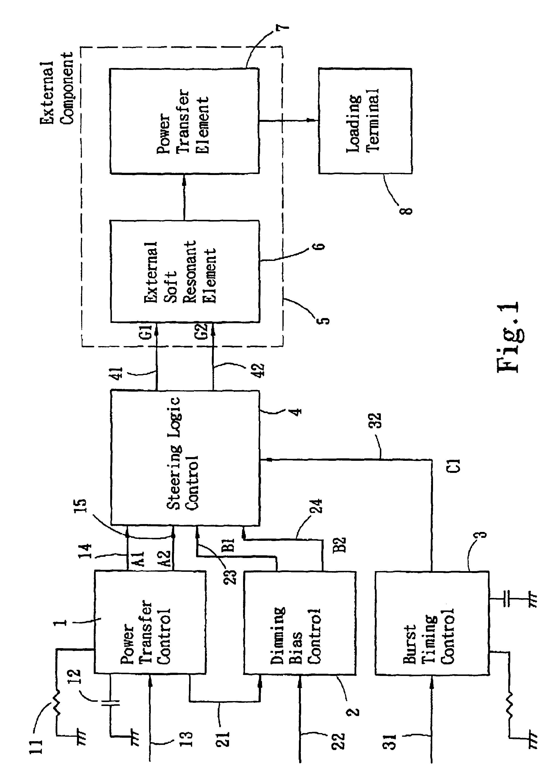
Please refer to FIGS. 1 to 5 for the present invention, the timing waveform of FIG. 1, and the schematic circuit of FIG. 1. As shown in the figures, the multi-period cycle-alternative switching mode power supply control device having a variable multi-period control cycle to effectively control certain power transfer elements of specific nature and assure those elements and the loading at the rear end can operate more efficiently in a reliable range of specific nature; said device comprises a power transfer control unit 1, a dimming bias control 2, a burst timing control 3, and a steering logic 4; wherein said power transfer control 1 is comprised of a resistor 11 and a capacitor 12 to constitute a determinant element for setting the oper...


PUM


Abstract

The present invention discloses to a multi-period cycle-alternative switching mode power supply control device, comprising: a power transfer control unit, a dimming bias control, a burst timing control, and a steering logic; wherein said device has a variable multi-period control cycle to effectively control certain power transfer elements of specific nature and assure those elements and the loading at the rear end can operate more efficiently in a reliable range of specific nature.

Description

FIELD OF INVENTIONThe present invention relates to a multi-period cycle-alternative switching mode power supply control device, more particularly to a power supply controller having a variable multi-period control cycle to effectively control certain power transfer elements of specific nature and assure those elements and the loading at the rear end can operate more efficiently in a reliable range of specific nature.BACKGROUND OF THE INVENTIONThe prior-art switching power supply controller is a controller primarily using the normal rate and variable frequency for the control as shown in FIG. 6. The charge and discharge of electricity of each oscillated circuit are set by means of connecting the resistor to the RT terminal, of which the RT terminal is connected to the FB terminal through the resistor to provide (controlled by light) a control frequency. CT1 is connected to the output terminal of the oscillated circuit of a capacitor, and capable of generating a trigonometric wave osc...

Claims


Application Information

Patent Timeline
IPC IPC(8): H02M3/04H02M3/156H02M3/335H02M3/24
CPCH02M3/33507H02M3/156
Inventor CHOU, CHIN-WENCHENG, EDDIECHUNG, BART CHIN-BIAU
Owner SHIN JIUH
Learn More