
Enhanced sampling rate in time domain imaging using MOEMS scanning optical delay line

a time domain imaging and optical delay technology, applied in the field of time domain imaging, can solve the problems of heavy system, unreliable, expensive, etc., and achieve the effect of improving the data acquisition in time domain imaging

Inactive Publication Date: 2005-01-04
MOTAMEDI MANOUCHEHR E +1
View PDF6 Cites 9 Cited by
  • Summary
  • Abstract
  • Description
  • Claims
  • Application Information

AI Technical Summary

Benefits of technology

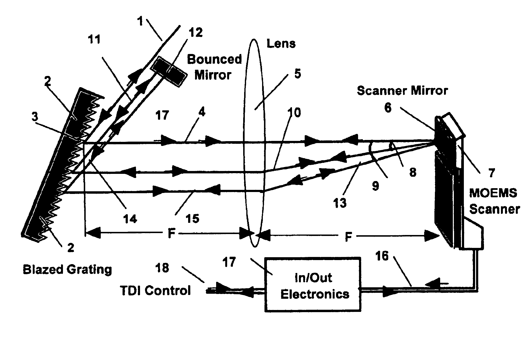
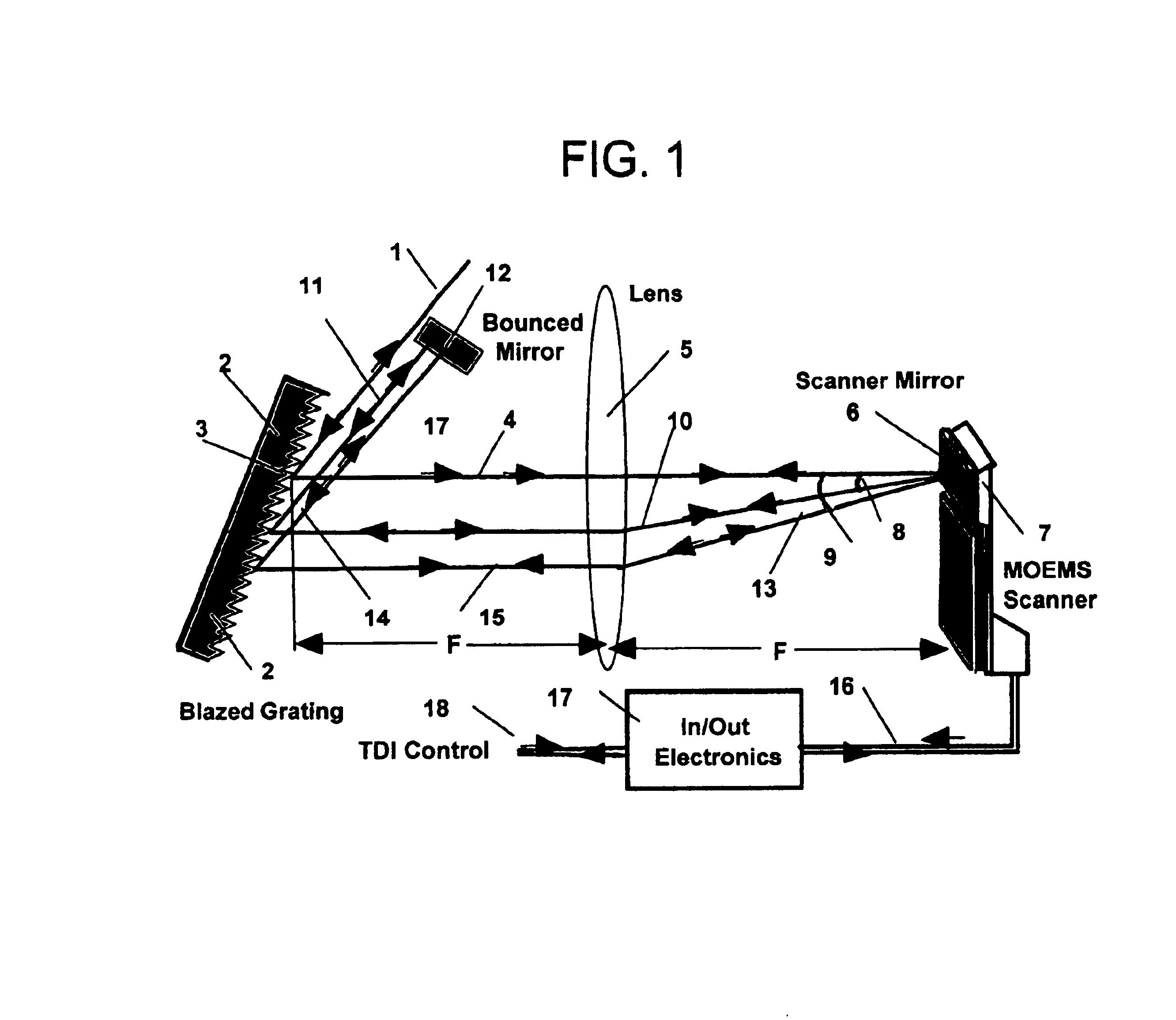
Electromagnetic waves in wide frequency ranges from microwave, terahertz, IR, to photonics have been used for applications to time-domain imaging. Time domain imaging requires an optical delay line capable of high-speed sampling (at least 100 Hz) and long enough time delay capacity on the order of 100 ps. The purpose of this invention is to introduce a miniature and rapid scanning optical delay line based on micro-opto-electro-mechanical system (MOEMS) technology to improve the data acquisition in time domain imaging for all applications requiring optical time delays up to or even beyond the 100 ps.

Problems solved by technology

These scanning systems could have a large size mirror, but such systems are heavy, expensive, and unreliable.

Method used


Image

  • Enhanced sampling rate in time domain imaging using MOEMS scanning optical delay line
  • Enhanced sampling rate in time domain imaging using MOEMS scanning optical delay line

Examples


Embodiment Construction

The disclosed apparatus is a miniature and rapid scanning optical delay line based on micro-opto-electro-mechanical system (MOEMS) technology. MOEMS is a new advanced technology as described in the special issue of Optical Engineering Journal, in “Micro-opto-electro-mechanical systems”, Optical Eng. Vol. 36, No. 5, May 1997. The disclosed apparatus improves the data acquisition in time domain imaging for all applications requiring time delays up to or even beyond the 100 ps and sampling rate of higher than 100 Hz.

The key to the disclosed method and apparatus is what we have achieved during the past several years in development of micro-optics and micro-electro-mechanics system (MEMS) and finally by merging these two advance technologies and creating a new worldwide used technology of MOEMS. The disclosed embodiment includes as a major component, an optical scanner that has been developed, tested, and which is in the process of being manufactured.

The development of presently disclose...


PUM


Abstract

Electromagnetic waves in wide frequency ranges up to photonics have been used for applications to time-domain imaging (TDI). Realistic time domain imaging requires a rapid optical delay line on the order of 100 ps with sampling rate at least 100 Hz. Present available optical time delay systems suffer either from low sampling rate or low time delay length, deviating from ideal requirements. The purpose of this invention is to introduce a miniature and rapid scanning optical delay line based on micro-opto-electro-mechanical system (MOEMS) technology to improve the data acquisition in time domain imaging, capable of sampling rate beyond 100 Hz and time delays beyond the 100 ps.

Description

FIELD OF THE DISCLOSED METHOD & APPARATUSThis Method and apparatus is related to time domain imaging and more specifically related to MOEMS scanning optical delay line.BACKGROUNDElectromagnetic waves in wide frequency ranges from microwave, terahertz, IR, to photonics have been used for applications to time-domain imaging (TDI). Time-domain imaging has potential to offer a solution in numerous applications ranging from medical diagnostics to security for package screening, color testing, and explosive detection. In spite of all these potential applications, time-domain imaging suffers for low sampling rate, which mainly is caused by the slow speed of its optical delay lines (ODL), which is a major component of TDI. In realistic time-domain imaging, an oscillatory optical time delay window of 100 ps at 100 Hz is required. Presently, such an ODL with this performance is not available. To arrange a time delay window of 100 ps, retro-refracting mirrors are used to oscillate with amplitu...

Claims


Application Information

Patent Timeline
Patent Type & Authority Patents(United States)
IPC IPC(8): G02B26/08
CPCG02B26/0866G02B26/0833
Inventor MOTAMEDI, MANOUCHEHR E.DABIRI, ALI E.
Owner MOTAMEDI MANOUCHEHR E
Learn More