Mesh connected electrical rotating machine with span changing

Inactive Publication Date: 2005-01-04
BOREALIS TECH LTD
View PDF9 Cites 88 Cited by
  • Summary
  • Abstract
  • Description
  • Claims
  • Application Information

AI Technical Summary

Benefits of technology

A technical advantage of the present invention is that high torque overload may be provided at low speeds whilst sufficient voltage is also provided for high-speed applications.

Problems solved by technology

In many cases, the cost of the inverter is considerably greater than the cost of the motor being supplied.
Whereas the alternating current machine itself may have substantial overload capability, and may carry currents of the order of five to ten times full rated current for periods measured in minutes, the overload capability of the inverter electronics is severely limited.
Exceeding the voltage or current ratings of the inverter electronics will swiftly cause device failure.
Voltage overload is normally not specified, and will cause near instantaneous destruction of semiconductor elements.
With any reasonably sized inverter, substantial motor overload capabilities remain untapped.
Electrical rotating machinery presents impedance that changes with mechanical load and rotational velocity.
In many traction application, there is limited available electrical power.
Thus requirements for high overload capability can only be met at low speed, where high torque is required for starting, but reduced speed means that mechanical power output is still low.
This increase in overload capability comes at a substantial cost.

Method used


Image

  • Mesh connected electrical rotating machine with span changing
  • Mesh connected electrical rotating machine with span changing
  • Mesh connected electrical rotating machine with span changing

Examples


examples

Specific examples are offered to enhance the disclosure and understanding of the present invention. These examples should in no way be considered limiting. These examples may be considered ‘best mode’ descriptions, in so far as the optimal motor for any given application will vary considerable with the mechanical requirements of the application. These descriptions will focus upon the differences between the present invention and the prior art, and as such will not focus upon details which are both well known in the art, and unchanged by the present invention, for example bearings or motor housing materials.

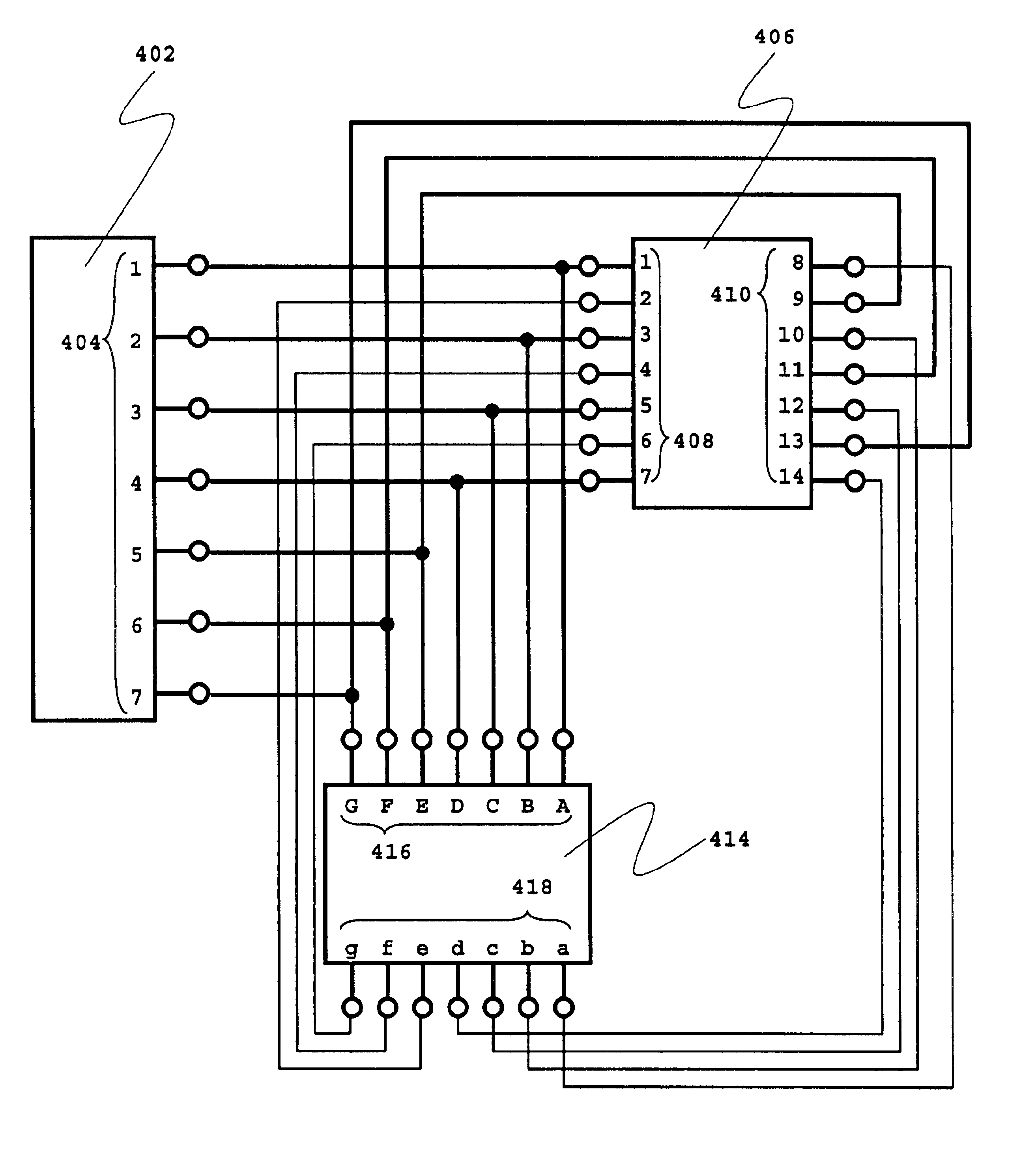
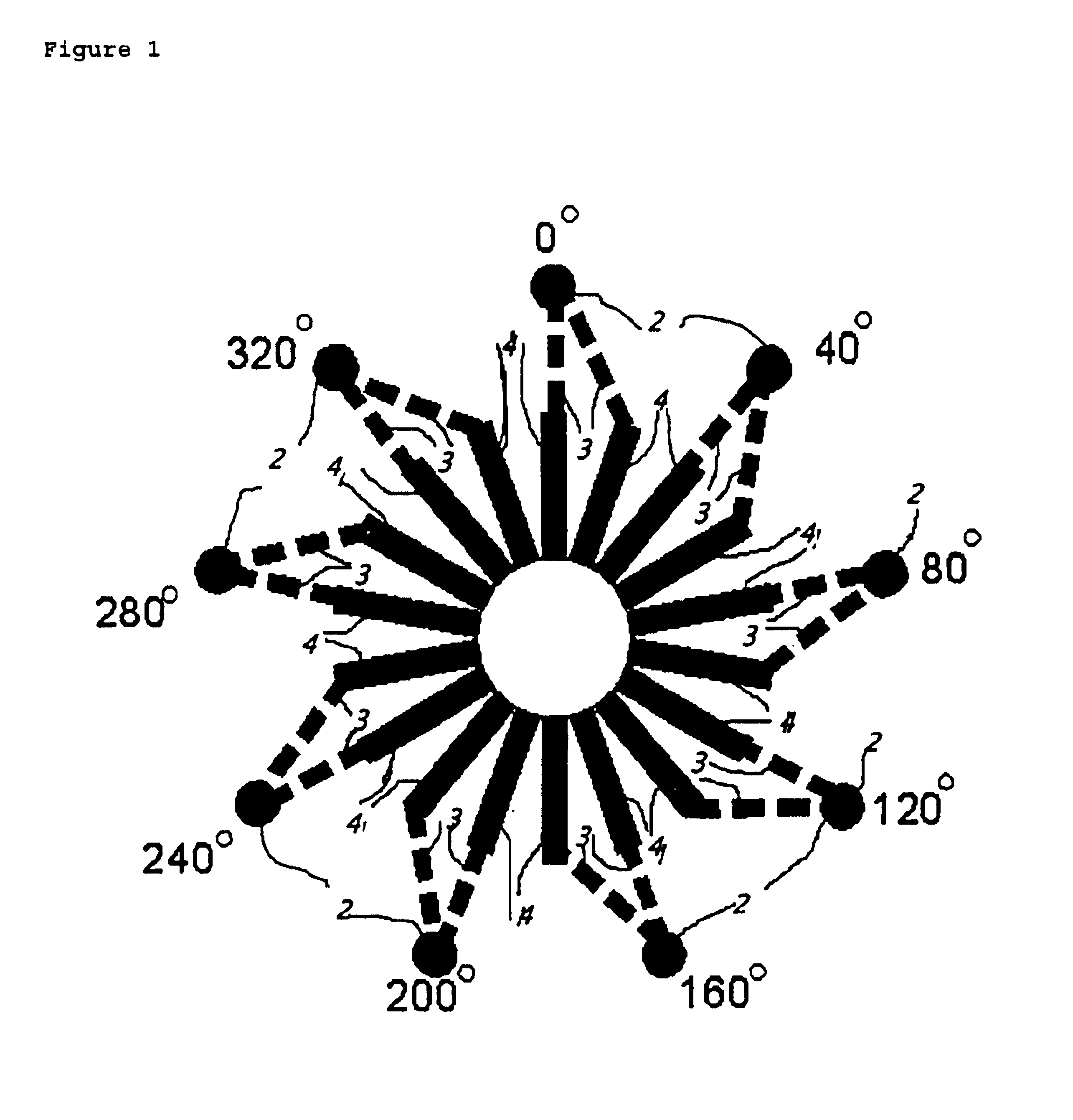
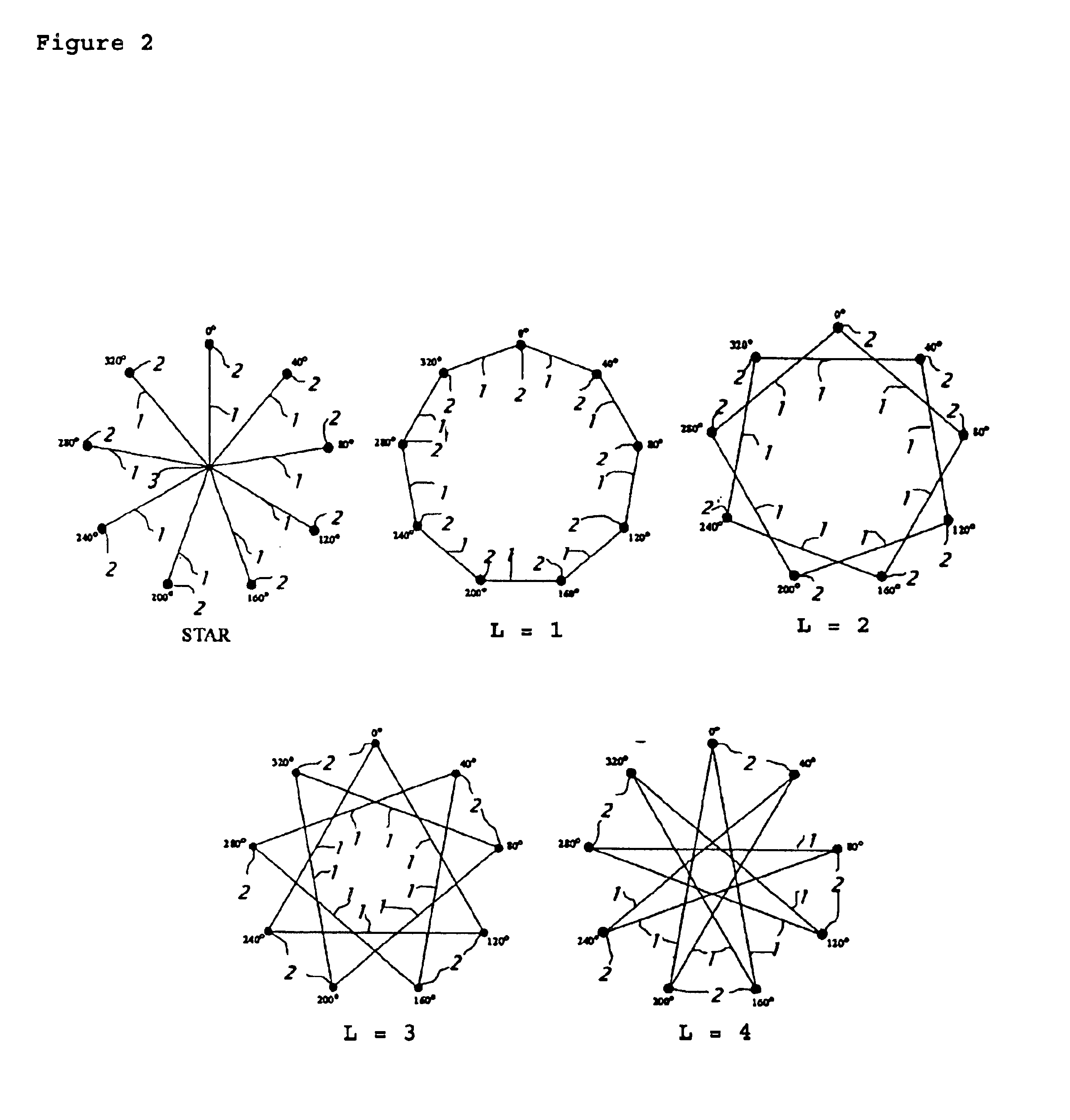
To better illustrate the scope of the present invention, Tables 2 to 7 and FIGS. 7 to 12 indicate the possible mesh connections and voltages for 5 to 15 phase devices. In the Tables, the value for V is the voltage across the windings when 1.0 volt is applied by a star connected source.

TABLE 25 Phase Mesh Connections.L = 1;L = 2;V = 1.176V = 1.902402406 1st406 2nd406 2ndTerminalPha...


PUM


Abstract

An electrical rotating apparatus is provided that has variable impedance. This is achieved by connecting one of the polyphase components of the apparatus in a mesh connection. The spanning value, L, of such a mesh connection may be varied by changing the harmonic content supplied by an inverter component. Also provided is a method for connecting an inverter to a motor, wherein a switching arrangement permits the simple alteration between various mesh connections of different span value, changing thereby the Volts / Hertz ratio of the motor.

Description

BACKGROUND OF THE INVENTIONThe present invention relates to motors and their inverter drives. In particular it related to methods and apparatus for connecting polyphase devices.An alternating current motor is commonly driven by an inverter. An inverter is a device capable of supplying alternating current of variable voltage and variable frequency to the alternating current motor, allowing for control of machine synchronous speed and thus of machine speed. The inverter may also be used with alternating current generators, and can cause an alternating current motor to act as a generator for braking applications. An alternating current motor may be an induction motor, a synchronous motor with either a wound rotor or permanent magnet rotor, or a brushless DC motor.In many cases, the cost of the inverter is considerably greater than the cost of the motor being supplied. It is thus necessary to minimize the size of the inverter power electronics in order to control system cost.Whereas the...

Claims


Application Information

Patent Timeline
IPC IPC(8): H02P25/18H02P29/00H02K3/28H02P27/00H02P25/16H02K17/02H02K17/12H02K5/22
CPCH02K3/28H02K11/0073H02P29/0038H02P25/18H02P25/22H02P27/00H02K17/12H02K5/225H02K11/33H02P29/50
Inventor EDELSON, JONATHAN SIDNEY
Owner BOREALIS TECH LTD
Why Eureka
Try Eureka