Secure enclosure for access to cabled systems

a secure enclosure and cabled system technology, applied in the installation of lighting conductors, electrical apparatus casings/cabinets/drawers, machine supports, etc., can solve the problem of difficulty in telling when a computer is present, and achieve the effect of easy fabrication, high strength and convenient opening

Inactive Publication Date: 2005-01-04
HOLOCOM
View PDF9 Cites 47 Cited by
  • Summary
  • Abstract
  • Description
  • Claims
  • Application Information

AI Technical Summary

Benefits of technology

More specifically, the invention is an enclosure for secure interconnection access to a cabled system by a user thereof, which comprises a housing having a back wall and a front wall connected by a peripheral wall, the walls defining an interior space in the housing, all joints therein being within the interior or on an interior side of the walls; the walls limiting user access to the interior space only through the front wall comprising an openable door, the door being hinged within the enclosure or on the interior side of the walls; a system connection member disposed in the interior and including interconnect means for connection to the system only through a service access opening in the back wall or the peripheral wall, the system connection member being configured for access thereto by only a single user at a time; and locking means for secure closure of the door; whereby access to the cabled system through the enclosure is available only to one user at a time and is visually identifiable and closure of the door securely prevents unauthorized access to the connection means and the system.

Problems solved by technology

While such linkages are convenient they are also quite insecure because it is difficult to tell when a computer is on, who is attached to the system at any time, and when the system is inaccessible.

Method used


Image

  • Secure enclosure for access to cabled systems
  • Secure enclosure for access to cabled systems
  • Secure enclosure for access to cabled systems

Examples


Embodiment Construction

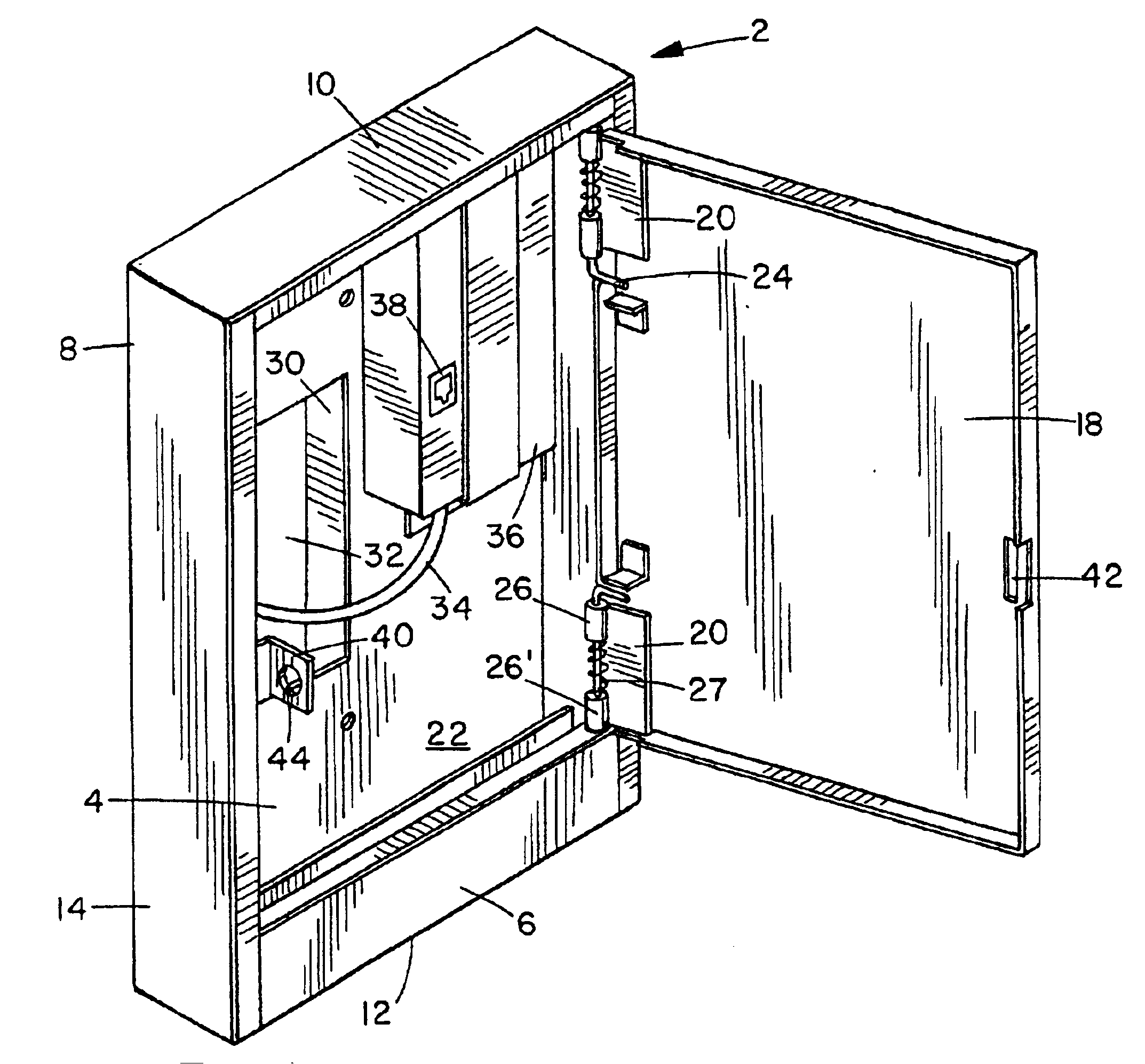
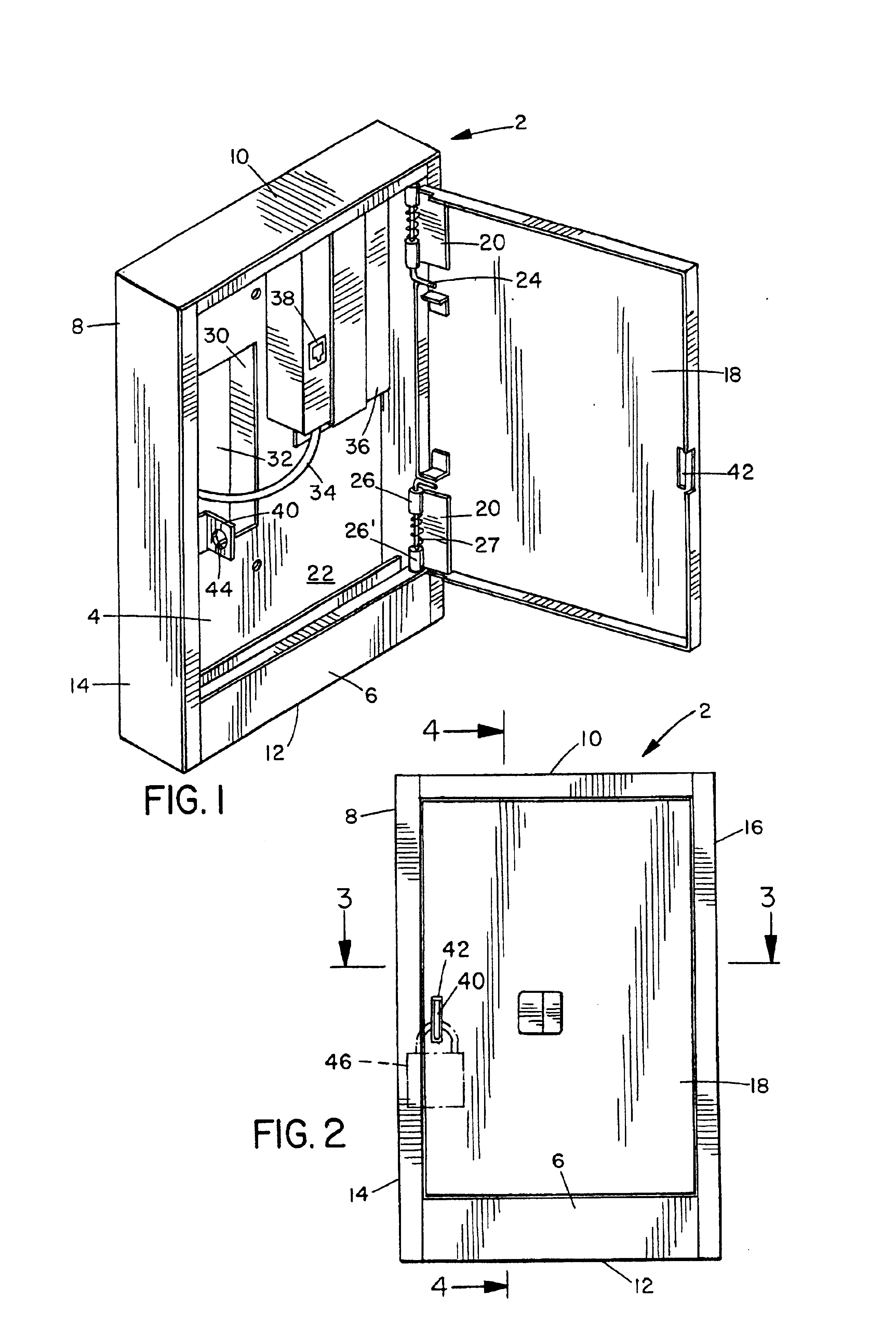
The invention herein can be best understood by reference to the drawings. The enclosure 2 is a box-like structure having a back wall 4, a front wall 6 and a peripheral wall 8 which is normally configured as four walls representing the top, bottom, and right and left side, as the enclosure would appear in a normal wall or pole mounting. For convenience these sides will be represented respectively by the numerals 10, 12, 14 and 16.

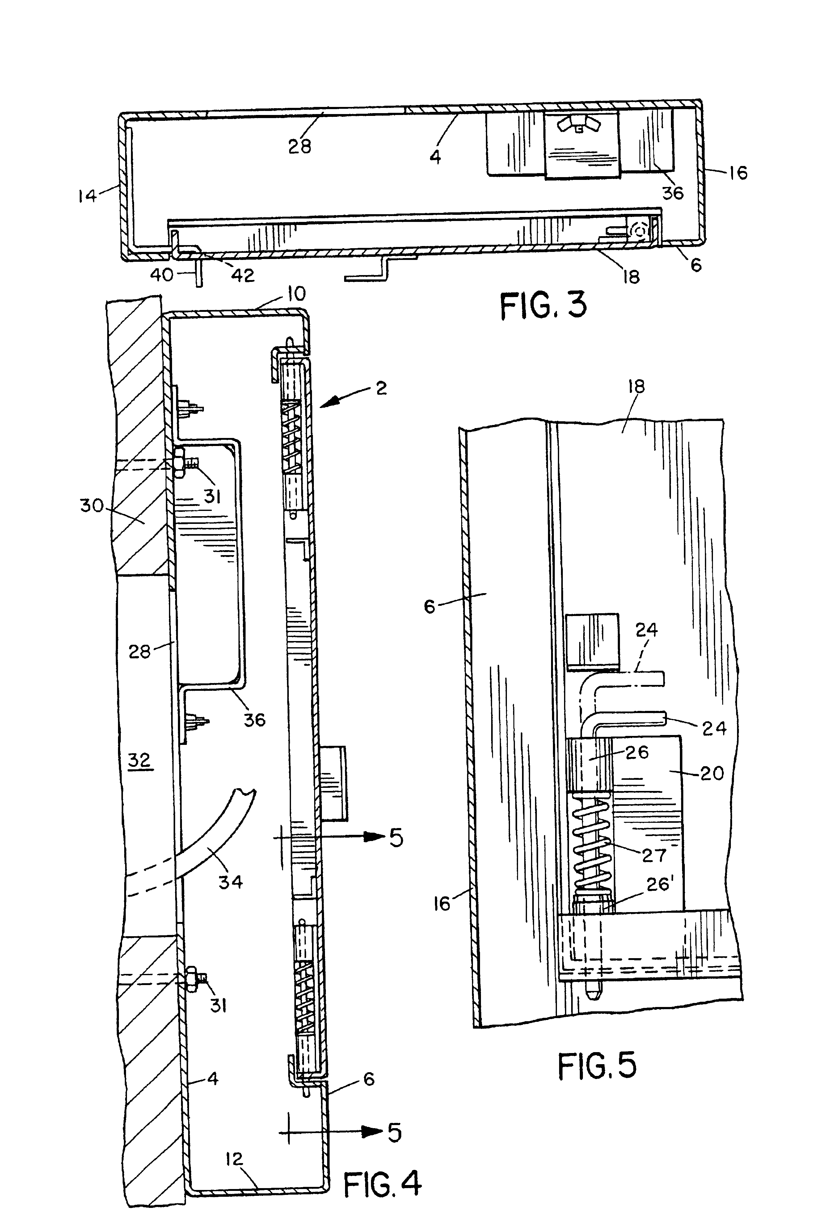
Mounted to the front wall 6 is an openable door 18. Door 18 is mounted on hinges 20, best illustrated in FIG. 5. The working mechanism of each hinge 20 is positioned within the interior of 22 of the enclosure so that no portion of the hinge 20 is accessible from outside the enclosure when the door 18 is closed. This prevents anyone from trying to open the enclosure by removing or tampering with the hinges 20. In many cases, however, it is convenient to have the door removed when access to the interior of the box is desired since the user's access cable for c...


PUM


Abstract

An enclosure is disclosed which is highly secure, permits access to a cabled network system only by one user at a time, permits visual and unequivocal observation of the security status of the enclosure, and prevents access to the interior thereof only by authorized persons. The enclosure has back, front and side walls and an interior, with all connections being internal. Limited interior access is provided only through a door and a service opening. Within the enclosure is a system connection device to the system, which is configured for access thereto by only a single user at a time. A lock secures door closure. Thus access to the cabled system through the enclosure is available only to one user at a time and must be obtained through the open door, with usage thereby being visually identifiable, and the door prevents unauthorized access.

Description

BACKGROUND OF THE INVENTION1. Field of the InventionThe invention relates an enclosure for user access to restricted cabled systems, such as cabled communication and computer networks, especially in a manner in which multiple user access at a given time is precluded and security status of the enclosure is visually apparent.2. Background InformationIn many company and government facilities, it is important for the employees to have access to exterior and interior secure computer networks, communication networks and other electronic systems. It is also important, however, for access to such systems out to be controlled and limited as to the identification of the people who are allowed to have such access, to have a means of insuring that the system is kept secure and that it can be determined who is using the system and when the system is accessible.At such company and government workplace facilities, access to a computer, electronic or communications network system is through compute...

Claims


Application Information

Patent Timeline
Patent Type & Authority Patents(United States)
IPC IPC(8): H02B1/00H02B1/44H04M1/02H04M1/667
CPCH02B1/44H04M1/0293Y10S248/906H04M1/667
Inventor HARRISON, MICHAEL B.MITCHELL, THOMAS E.
Owner HOLOCOM
Why Eureka
Try Eureka