
Pedal actuated height adjustment mechanism for a mower cutting deck

a technology of height adjustment and mower, which is applied in the direction of mowers, agriculture tools and machines, etc., can solve the problems of operator injury, inability to adjust the height of the above structure, and inability to push or pull the above structure, etc., to achieve the effect of easy determination of the positioning of the deck, minimal effort, and easy adjustmen

Inactive Publication Date: 2005-01-04
DEERE & CO
View PDF22 Cites 47 Cited by
  • Summary
  • Abstract
  • Description
  • Claims
  • Application Information

AI Technical Summary

Benefits of technology

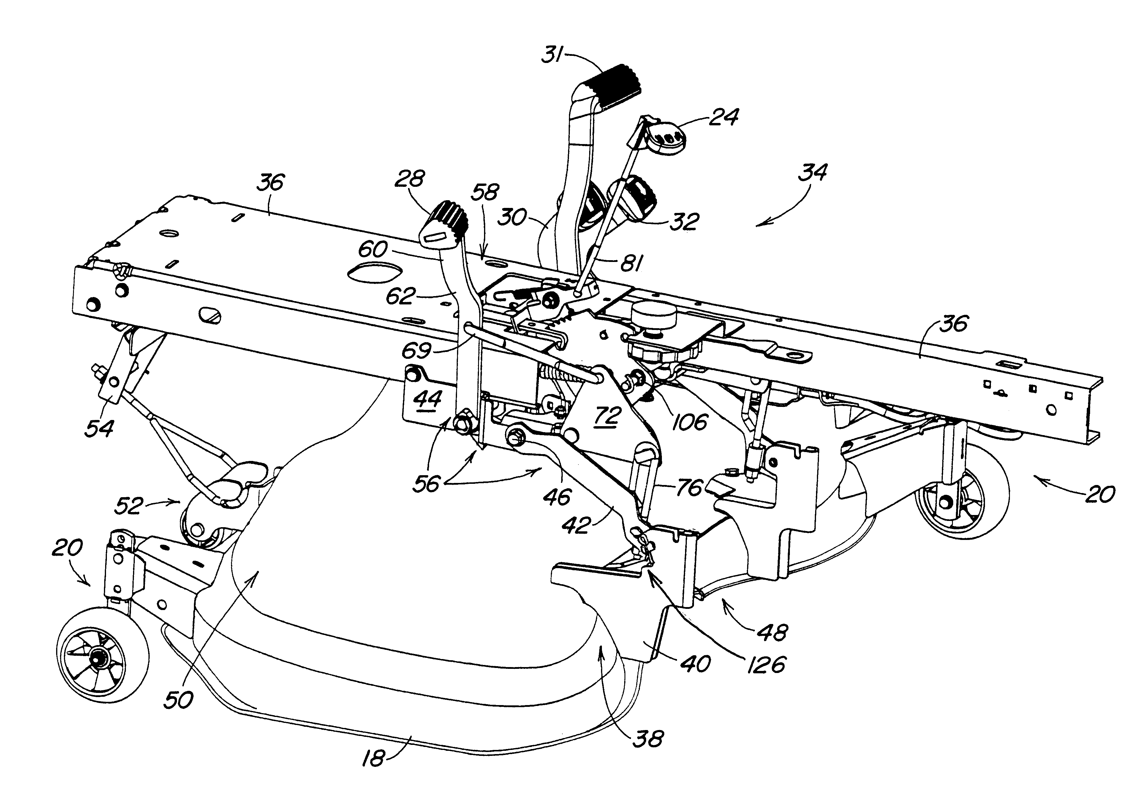
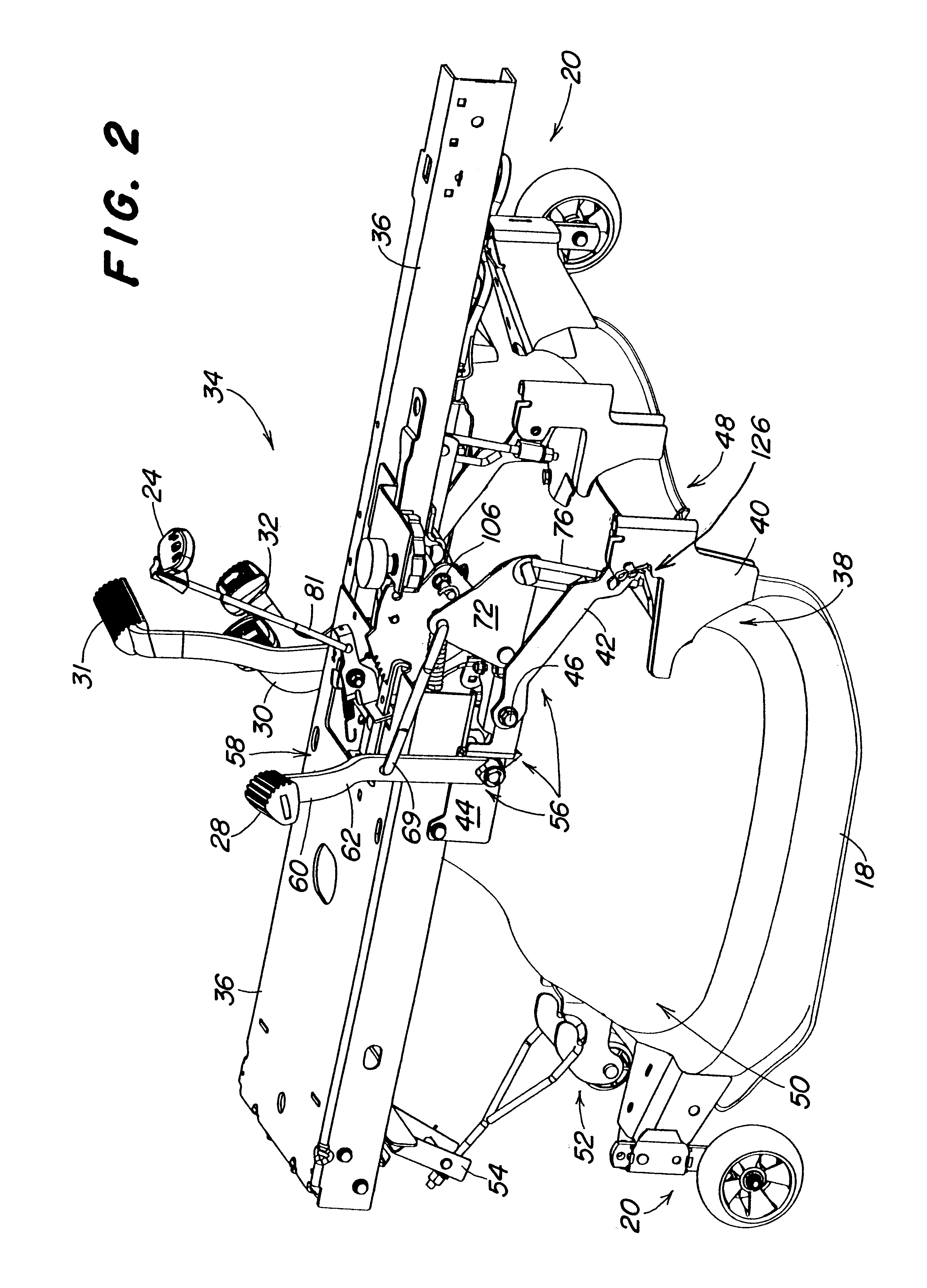
The present invention provides a lift assembly for controlling the height of a cutting deck relative to the ground. The assembly includes a pedal actuated adjusting assembly and a manually operable latching system. The deck can be locked in a plurality of positions to clear obstacles or remove the deck from the mower. The assembly also includes an indicator to easily determine the positioning of the deck while seated on the mower. The handle is placed directly in front of the operator and is within an arm's reach of the operator's touch. The user can expend minimal effort in achieving adjustment of the deck and can easily determine the height of the adjustment above the ground surface.

Problems solved by technology

Exertion of force in either of these manners is often strenuous and tiring requiring the user to gather a certain amount of upper body strength to obtain any adjustment of the deck.
Additionally, such exertion may cause an operator injury due to strain resulting from the operator being pulled from or out of the seating apparatus.
Even more simply, having to either push or pull on the above structure is inherently uncomfortable because of the mere tendency to be unstationary while trying to remain seated on the mower.
While allowing desired securement of the deck in the locked position, it is many times difficult to visually determine the placement of the handle or formation while seated on the mower.
The difficulty arises because the operator must exert additional effort in confirming whether the handle or formation is in a locked position since the components are either to the side of the mower's seat or at a distance from the seat, respectively.

Method used


Image

  • Pedal actuated height adjustment mechanism for a mower cutting deck
  • Pedal actuated height adjustment mechanism for a mower cutting deck
  • Pedal actuated height adjustment mechanism for a mower cutting deck

Examples


Embodiment Construction

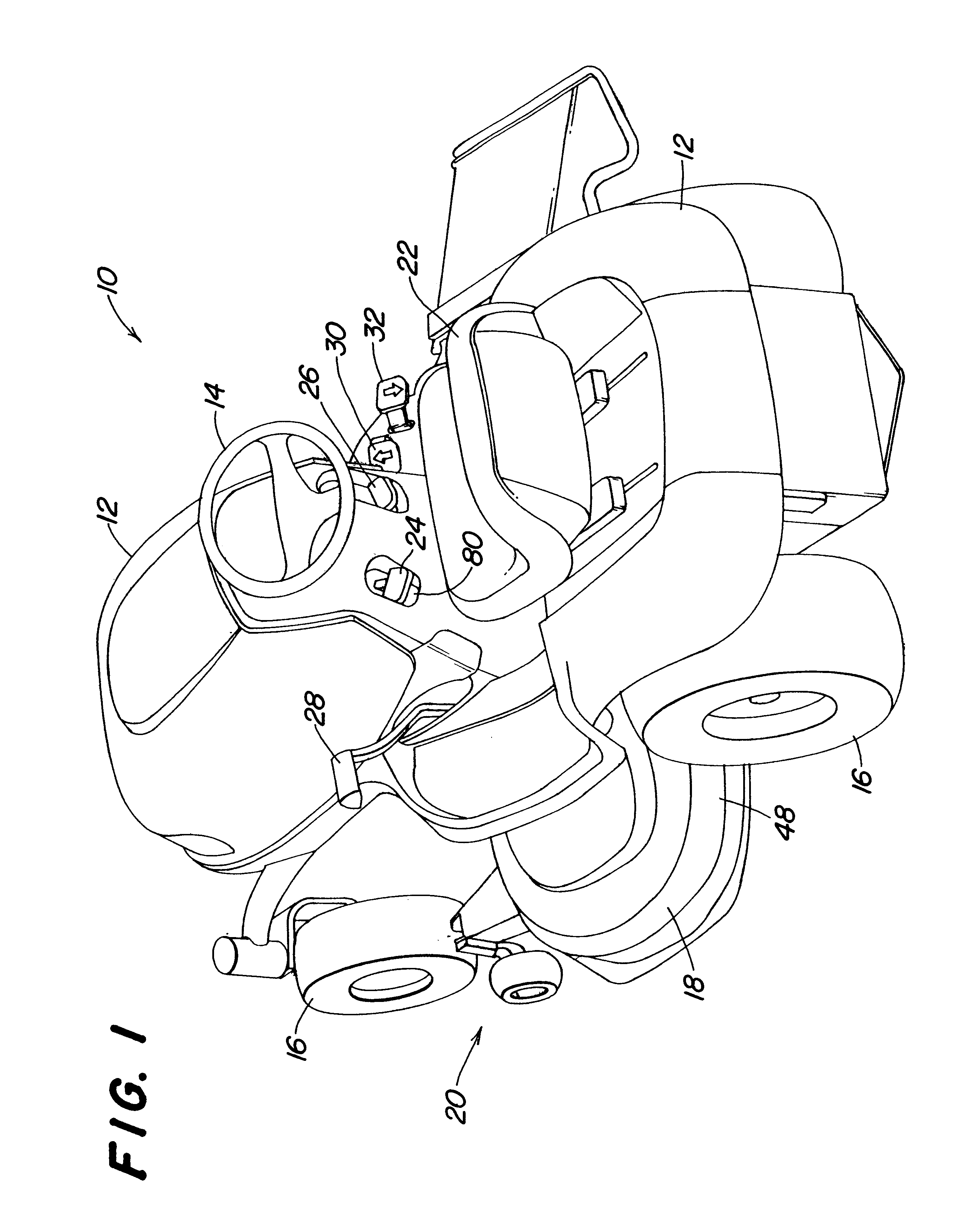
As shown in FIG. 1, there is illustrated a riding mower 10 having a cover 12, steering wheel 14, wheels 16, and an attached cutting deck 18 having ground wheel assemblies 20 adapted to serve as anti-scalp wheels. Also attached with the mower is a seating apparatus 22 for accommodating an operator. Positioned directly in front of the seat are manually operable handles 24,26 on both the operator's left and right hand side, respectively, when looking forwardly of the seat 22. To the left of the seat 22, there is provided a pedal 28 for use in adjusting the height of cutting deck 18 above the surface of the ground. To the right of the seat are shown two drive pedals 30,32, one indicating forward motion and the other indicating rearward motion, both pedals made available for controlling the mower's drive direction when in use. controlling the mower's drive direction when in use.

Shown in FIG. 2 is the lift assembly 34 according to the present invention in a locked position in which the de...


PUM


Abstract

A lockable lift assembly for controlling the height of a mower cutting deck is provided. The assembly includes a pedal actuated system including a rockshaft extending the width of the mower frame and having plates on which the deck is carried as a change in height is either performed or maintained. Intermediate these extensions is a toothed plate which cooperates with a handle operated latching system to permit a user to fixedly control the height of the cutting deck. Joint use of the pedal and latching system enables placement of the deck in a position wherein the deck is raised above the highest heighth of cut for travel across the ground or, alternatively, in a removal position in which the deck may be securely and quickly detached from the mower.

Description

BACKGROUND OF THE INVENTION1. Field of the InventionThe present invention relates to height adjustable mower cutting decks, and more specifically, to structure permitting the adjustment of such decks between a locked and unlocked position.2. Description of Related ArtVegetation cutting implements such as mounted cutting decks are typically carried by riding mowers having structure allowing adjustment of those decks between a range of heights above ground level. Ordinarily, the range extends between a position at or below the lowest available cut height to a position at or above the highest available cut height. Adjustment to a position below the cut heighth range is frequently preferred for ease in removal of the deck from the mower since the deck is that much closer to the ground surface. Alternatively, adjustment above the cut heighth range is favored to permit the deck to clear obstacles encountered while travelling across the ground.Adjustment of the cutting decks is presently a...

Claims


Application Information

Patent Timeline
Patent Type & Authority Patents(United States)
IPC IPC(8): A01D34/64A01D34/63
CPCA01D34/64Y10S56/22A01D2101/00
Inventor SWARTZENDRUBER, JAMES ALLENHELD, BRIAN GEORGE
Owner DEERE & CO
Learn More