Low-voltage high-speed frequency-divider circuit
a frequency divider circuit and low-voltage technology, applied in the direction of pulse technique, continuous circulation pulse counter, count chain synchronous pulse counter, etc., can solve the problem of limited minimum required supply voltage (v.sub.dd) and conventional frequency dividers at a low supply voltag
- Summary
- Abstract
- Description
- Claims
- Application Information
AI Technical Summary
Benefits of technology
Problems solved by technology
Method used
Image
Examples
Embodiment Construction
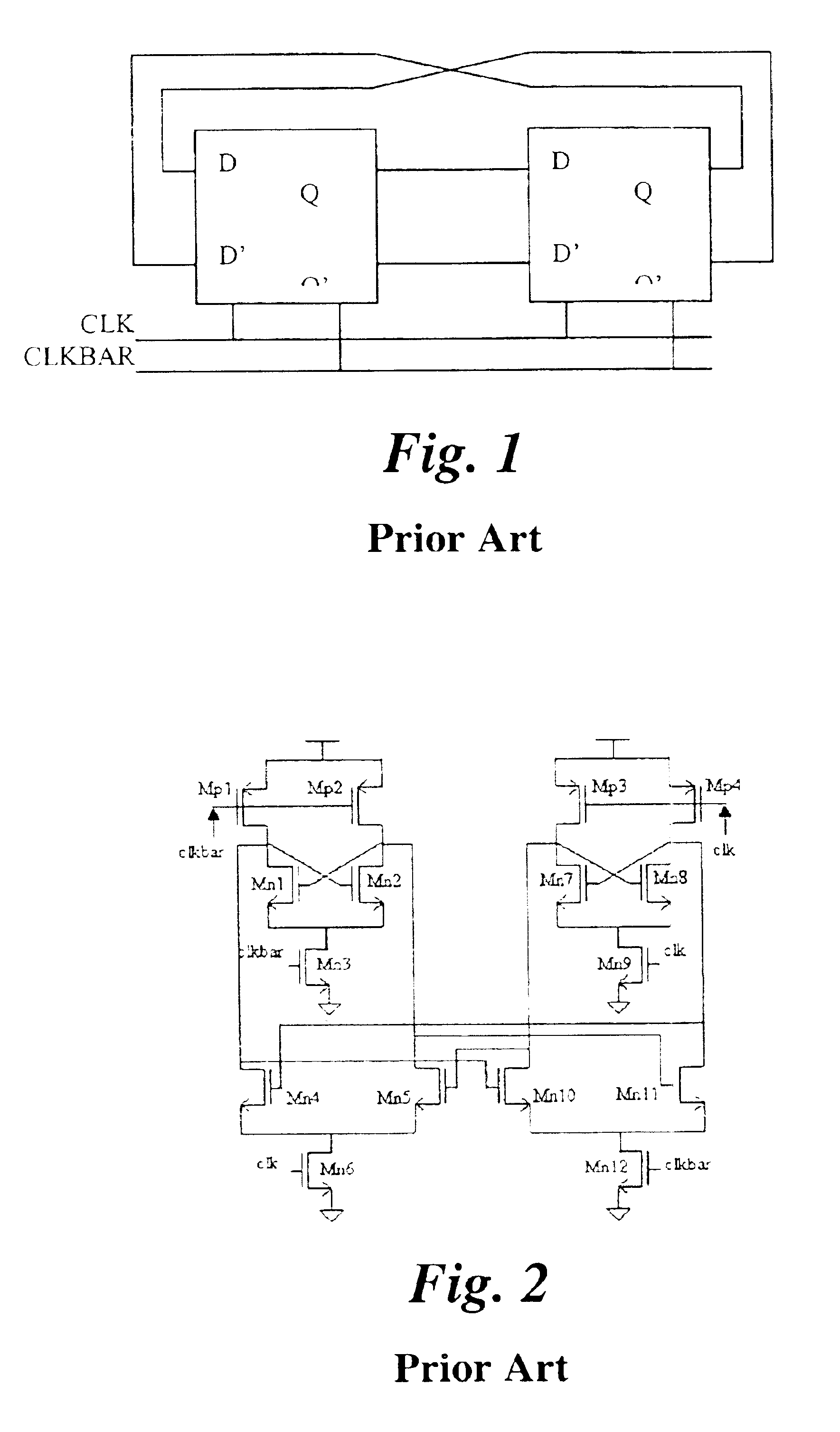
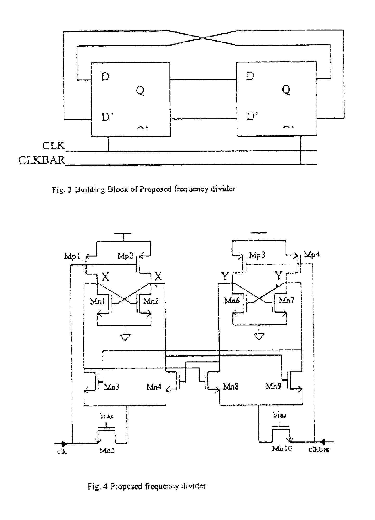
FIG. 3 shows the building blocks of an embodiment of the present invention and its schematic is shown in FIG. 4. The proposed frequency divider consists of two identical D-flip-flops cross-coupled with each other. Each circuit section generates an output signal driving the other, in other words the outputs of the first D-flip-flop are connected to the inputs of the second D-flip-flop, and similarly the outputs of the second D-flip-flop are fed back to the first D-flip-flop inputs. Unlike conventional frequency divider designs that employ a pair of complementary input signals within each D-flip-flop section, each of the D-flip-flops in the circuit of FIG. 3 is driven with a single input signal only. In this embodiment of the present invention, the first D-flip-flop is driven by an input signal (CLK), while the second D-flip-flop is driven by an input signal (CLKBAR), which is the complementary counterpart of CLK. The function of the two identical D-flip-flops is in a cooperative rela...
PUM
 Abstract
Description
Claims
Application Information
 - R&D
- Intellectual Property
- Life Sciences
- Materials
- Tech Scout
- Unparalleled Data Quality
- Higher Quality Content
- 60% Fewer Hallucinations
Browse by: Latest US Patents, China's latest patents, Technical Efficacy Thesaurus, Application Domain, Technology Topic, Popular Technical Reports.
© 2025 PatSnap. All rights reserved.Legal|Privacy policy|Modern Slavery Act Transparency Statement|Sitemap|About US| Contact US: help@patsnap.com


