Eureka AIR delivers breakthrough ideas for toughest innovation challenges, trusted by R&D personnel around the world.

Pipe repair clamp

a technology for fixing clamps and pipes, applied in the direction of snap fasteners, buckles, mechanical devices, etc., can solve the problems of inability to provide pipes and other cylindrical bodies with such flanges to be coupled by devices of this type, prior-art pipe couplings may have limited applications, and devices are quite complex, so as to achieve the flexibility easily, reduce diametrical flexibility, and increase the diameter of the pip

Inactive Publication Date: 2004-12-14
KRAUSZ INDS DEVMENT
View PDF27 Cites 59 Cited by
  • Summary
  • Abstract
  • Description
  • Claims
  • Application Information

AI Technical Summary

Benefits of technology

It is a further object of the present invention to provide a wide-range pipe repair clamp provided with improved fastening means.
It is yet a further object of the present invention to provide a wide-range pipe repair clamp at moderate cost by use of a simple tension band to squeeze a flexible high-friction liner against the outer surface of the pipe.
d) said plurality of screw fasteners inserted into said apertures wherein the tightening of said screw fasteners reduces the size of said triangularly shaped space and tightens said metal clamping band to compress said flexible inner sleeve sealingly against the outer diameter of said pipes.
In contradistinction thereto the present invention uses a plain band without any bent-over lips visible when viewed in a longitudinal cross-section, thus easily achieving the required flexibility. Axial extrusion of the flexible inner sleeve can be prevented without providing end walls--this being the subject of one of our co-pending patent applications.
It will thus be realized that the novel clamp of the present invention serves to provide an economically viable device for repairing of pipes. Larger pipe diameters are accommodated simply by using a longer steel band and larger rubber sleeve, thus the larger the pipe diameter the greater the cost advantage relative to other designs.
The drawings show elastomer caps fitted over the screw ends. While not functionally essential, the caps improve the appearance of the coupling, make handling the coupling more pleasant, prevent inadvertent loss of the nut and washer, and protect the screw ends from possible damage.

Problems solved by technology

Pipes and other cylindrical bodies not provided with such flange can not be coupled by devices of this type.
Such limitation is satisfactory where the outer diameter of the pipeline to be serviced or extended is known in advance.
However as field service workers may need to deal with pipes made according to different standards and made of various metals or plastics, prior-art pipe couplings may have limited applications.
The device is however quite complex, and is not intended to cope with large diameter variations.
Anchoring of the band extremities was however found to be limited, and the band was not utilized to provide a support for the screw clamps.

Method used


Image

  • Pipe repair clamp
  • Pipe repair clamp
  • Pipe repair clamp

Examples


embodiment 42

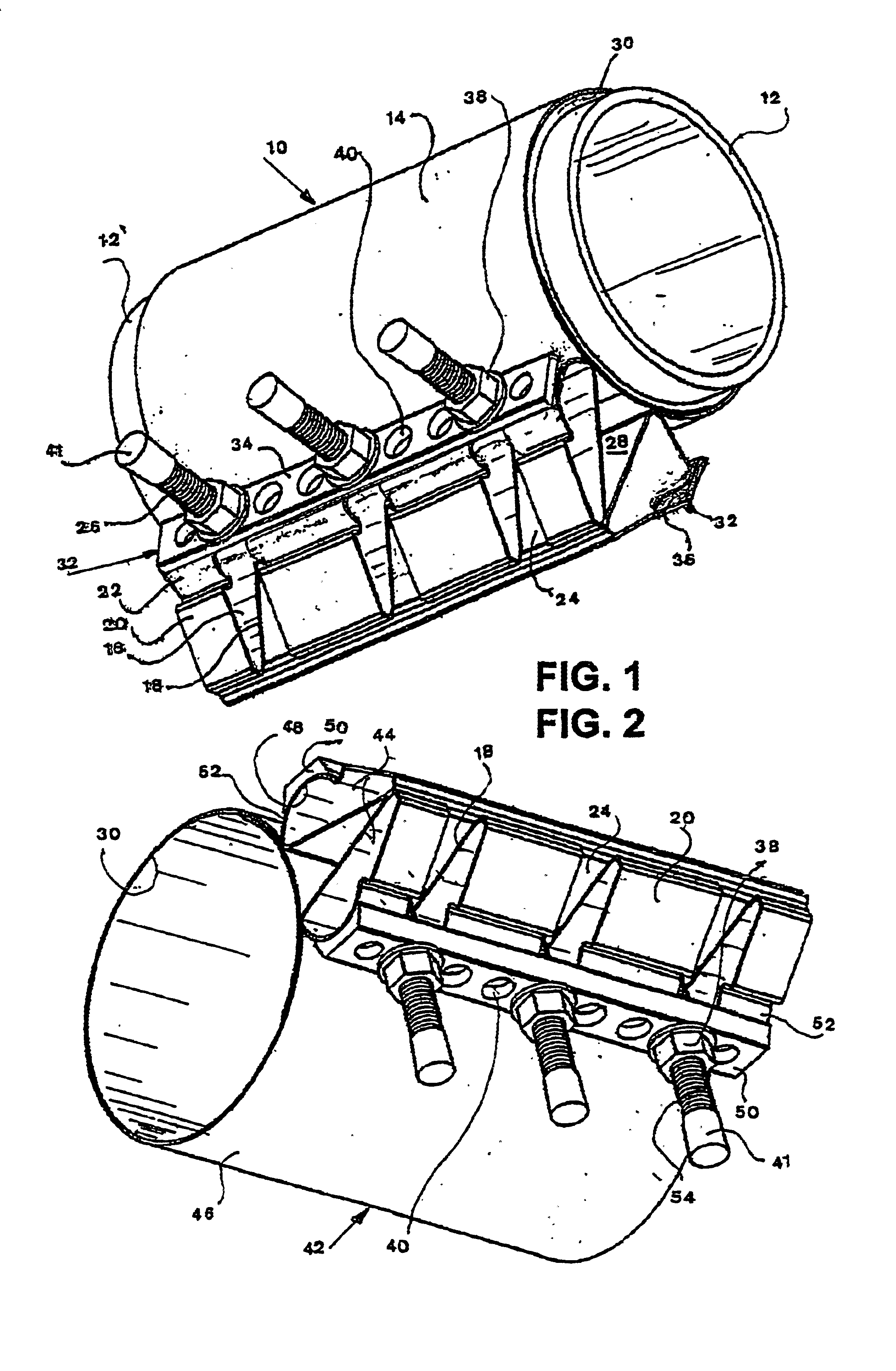
FIG. 2 illustrates an embodiment 42 which is helpful in retaining the desired shape of the hollow shapes 44 formed by the clamp band 46 extension.

The inner major face 48 of the profile strips 50 which contacts the outer surface of the convex rounded section 52 is concave. The radius of curvature matches the radius of curvature of the convex rounded section 52. When the screw fasteners 54 are tightened to close the coupling 42 around a pipe 12 (seen in FIG. 1), the face 48 distributes pressure evenly and so avoids distortion of the hollow shape 44.

embodiment 56

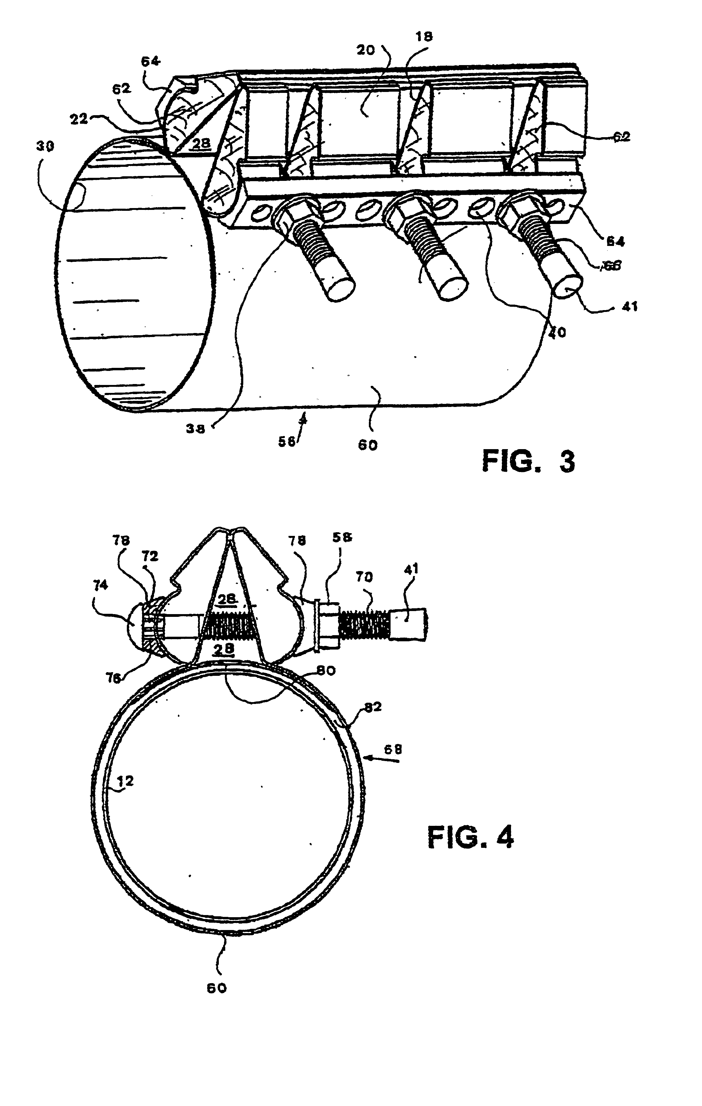
Referring now to FIG. 3, there is seen a further embodiment 56 of the wide-range pipe clamp coupling. The hollow shapes formed at both ends of the band 60 are filled with a crush-resistant material 62, such as wood or a closed-cell foamed plastic. The material 62 allows the use of a thinner metal sheet band 60, which could not be used otherwise due to the compressive force applied by the profile strip 64 when the screw fasteners 66 are tightened. The filling material 62 retains the desired shape of the hollow shape whatever the thickness of the metal clamping band 60.

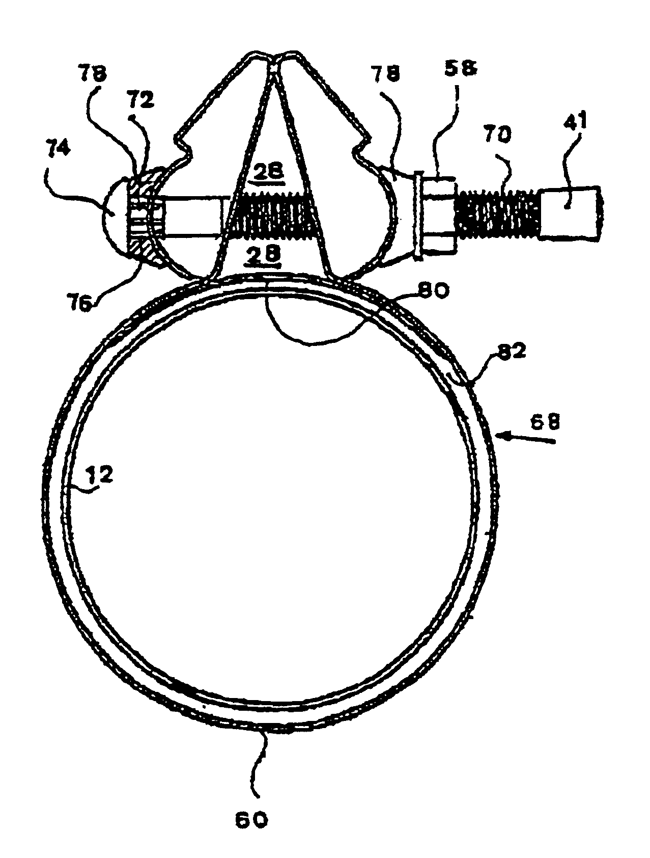
Seen in FIG. 4 is a detail of a wide-range pipe clamp 68. The screw fasteners 70 are provided with a non-circular neck 72, for example having splines, serrations or a hexagonal section, adjacent to the fastener head 74. When the screw fastener is tightened the neck 72 bites into the aperture 76 of the profile strip 78. This prevents the screw fastener 70 from revolving about its own axis while a nut 58 is being tightene...


PUM


Abstract

The present invention relates to a repair clamp providing an improved pipe repair clamp. The clamp according to the invention could be used in some cases as a coupling to join two pipe ends.The clamp comprises;a) a metal clamping band to surround 3600 of a pipe. The band being extended at both ends to form a hollow shape including a flat base, a wedge-shaped section and a convex rounded section, elongated apertures being provided to allow passage for screw fasteners through the hollow shape, narrow edges of the wedge-shaped sections being in contact with each other to form a substantially triangularly shaped space between the formed ends; and a flexible inner sealing sleeve disposed inside the clamping band and a pair of profile strips each having a major face for contacting the outer surface of the convex rounded section, and an opposite seating face for shoulder support of a plurality of screw fasteners, the strips having apertures to allow passage of the fasteners, and a plurality of screw fasteners inserted into the apertures wherein the tightening of said screw fasteners reduces the size of the triangularly shaped space and tightens the metal clamping band to compress the flexible inner sleeve sealingly against the outer diameter of the pipes.

Description

BACKGROUND AND FILED OF THE INVENTIONThe present invention relates to a repair clamp.More particularly, the invention provides an improved pipe repair clamp. The clamp according to the invention could be used in some cases as a coupling to join two pipe ends.Where extensions, repairs or replacements have to be carried sometimes out under field conditions it is usually much easier to use pipe clamps which do not requiring welding. Furthermore if the work is to be carried out near flammable materials welding will be prohibited, and other methods must be used.Many prior art pipe couplings are designed to squeeze together a pair of sloping side flanges assumed to be strongly attached or integral with the pipes. Examples of this type of coupling are seen in U.S. Pat. No. 4,568,115 to Zimmerly, U.S. Pat. No. 4,722,561 to Heckethorn et al., U.S. Pat. No. 4,919,453 to Halling et al., U.S. Pat. No. 5,277,458 to Tschann, U.S. Pat. No. 5,509,702 and U.S. Pat. No. 5,645,303 to Warehime et al., ...

Claims


Application Information

Patent Timeline
Patent Type & Authority Patents(United States)
IPC IPC(8): F16L55/16F16L55/172
CPCF16L55/172Y10T24/1441F16L21/005F16L21/065
Inventor KRAUSZ, ELIEZERCHIPROOT, AVI
Owner KRAUSZ INDS DEVMENT
Why Eureka
Eureka Blog
Learn More