
Variable length decoder and decoding method

a decoder and variable length technology, applied in the field of variable length decoder and decoder, can solve the problem of reducing the possibility of erroneously decoding an incorrect code word as a correct code word, and achieve the effect of reducing the influence of the frame error

Inactive Publication Date: 2004-12-07
KK TOSHIBA
View PDF15 Cites 70 Cited by
  • Summary
  • Abstract
  • Description
  • Claims
  • Application Information

AI Technical Summary

Benefits of technology

In this variable-length decoding apparatus, when errors are detected by the forward and backward decoders, the decode value determination unit is notified of the error detection positions as two types of position information, i.e., positions in units of bits and positions in units of syntax. The true error position can therefore be checked doubly on the basis of the error detection positions in units of bits and the error detection positions in units of syntax. This allows the use of only decode results corresponding to correct code words with a considerably high probability, and hence can decreases the possibility of erroneously decoding an incorrect code word as a correct code word.
In general, owing to the characteristics of a video encoding scheme, to determine an incorrect portion as a correct portion influences the display frame more than to discard a correct portion. Therefore, by performing a double check based on error detection positions in units of bits and syntax, the influences exerted in the display frame when an incorrect portion is determined as a correction can be greatly reduced.

Problems solved by technology

This allows the use of only decode results corresponding to correct code words with a considerably high probability, and hence can decreases the possibility of erroneously decoding an incorrect code word as a correct code word.

Method used


Image

  • Variable length decoder and decoding method
  • Variable length decoder and decoding method
  • Variable length decoder and decoding method

Examples


first embodiment

(First Embodiment)

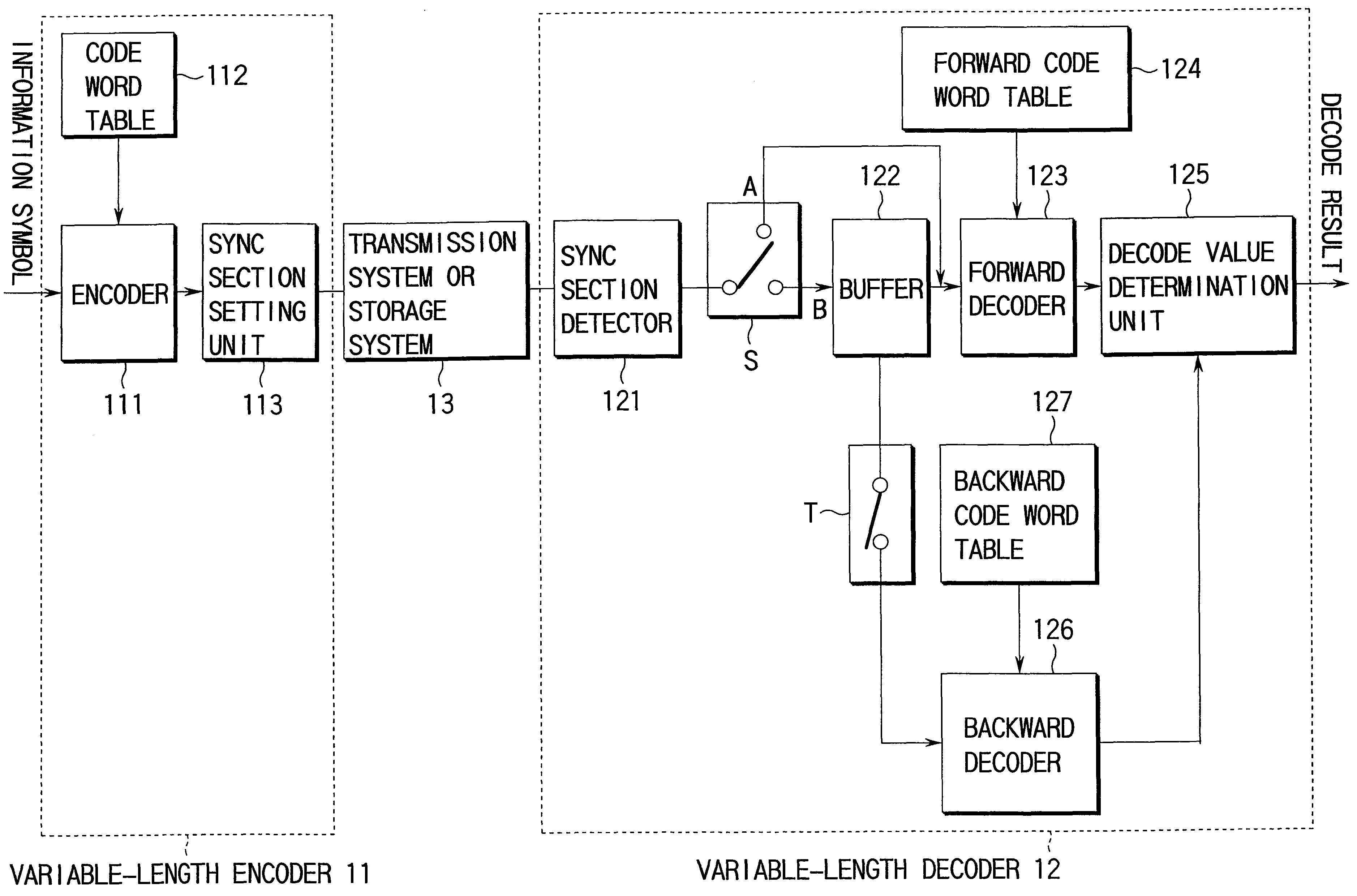
FIG. 5 shows the arrangement of a variable-length encoding / decoding apparatus according to an embodiment of the present invention. This variable-length encoding / decoding apparatus generates variable-length-encoded data and decodes it. A sync code is periodically inserted in variable-length-encoded data. As a variable length code, a reversible code (Reversible VLC) that can be decoded in the two directions, i.e., the forward and backward directions, like those described above, is used.

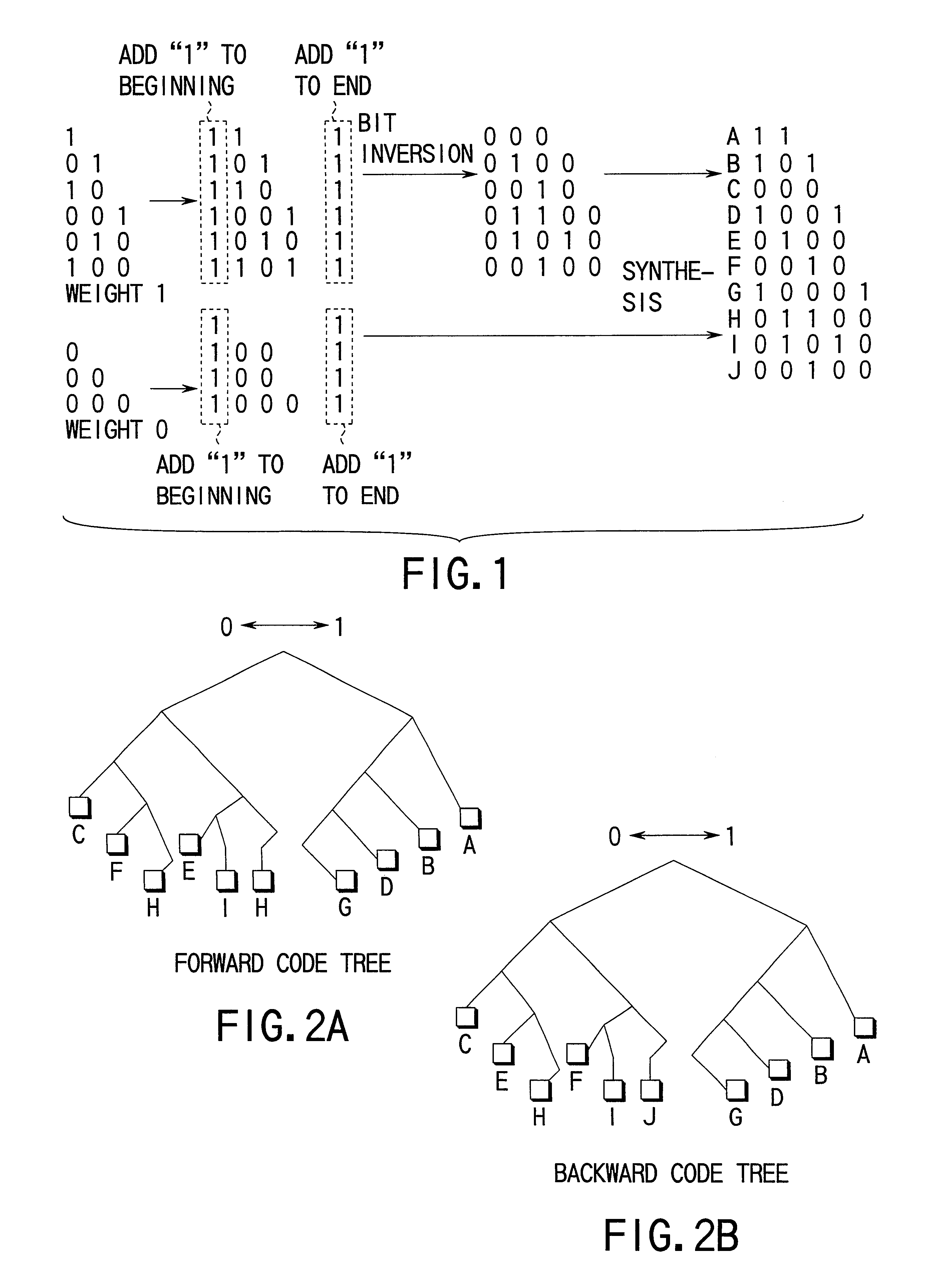
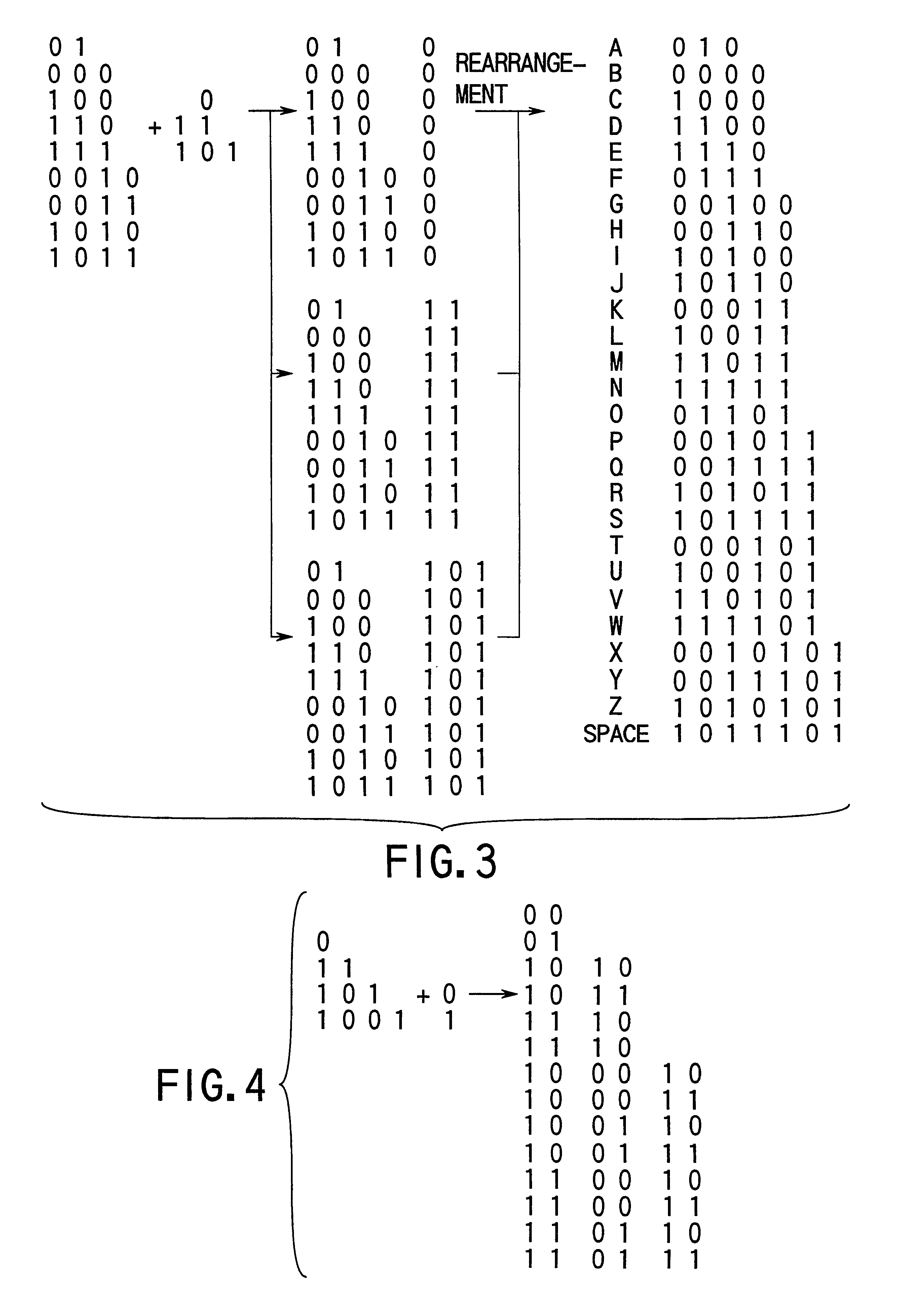
As shown in FIG. 5, a variable-length encoding apparatus 11 is constituted by an encoder 111, a coded word table 112, and a sync section setting unit 113. The coded word table 112 stores variable length code words prepared in correspondence with information symbols in accordance with the reversible code word forming methods described with reference to FIGS. 1 to 4. The coded word table 112 also stores reversible codes, which can be decoded in both the forward and backward directions, i...

second embodiment

(Second Embodiment)

FIG. 10 shows the arrangement of a variable-length encoding / decoding apparatus for video signals according to the second embodiment of the present invention.

This video encoding / decoding apparatus is made up of a video encoder 21, a video decoder 22, and a transmission system or storage system 23.

In the video encoder 21, the data encoded by a data source encoder 202 is divided into upper layer data and lower layer data by a video multiplexer 203, and the respective data are variable-length encoded. These upper and lower layer data are multiplexed, and sync section setting and the like are performed. The resultant data is smoothed by a transmission buffer 204. The resultant data is then sent as encoded data to the transmission system or storage system 23. An encoding control unit 201 controls the data source encoder 202 and the video multiplexer 203 in consideration of the buffer amount of the transmission buffer 204.

In the video decoder 22, the encoded data from th...

third embodiment

(Third Embodiment)

An error range estimating method which can be applied to decode value determination processing in the first and second embodiments will be described as the third embodiment of the present invention.

FIG. 51 is a block diagram showing the arrangement of a variable-length decoder 109 according to the third embodiment of the present invention.

The variable-length decoder 109 is designed to decode encoded data containing variable length codes in units of sync sections as in the first and second embodiments, and has the same basic arrangement as that of the first and second embodiments.

In the variable-length decoder 109, when encoded data is a variable length code that can be decoded only in the forward direction, a switch S is connected to A, and normal forward decoding is performed by a forward decoder 104. The encoded data decoded by the forward decoder 104 is sent to a decode value determination unit 105.

When the encoded data is a reversible variable length code that ...


PUM


Abstract

Encoded data using reversible variable length code words is input to a forward decoder (123) to be decoded in the forward direction. When an error is detected in the encoded data in the forward decode processing, backward decode processing is started by a backward decoder (126). A decode value determination unit (125) determines a decode value by using the forward and backward decode results and the error detection positions in the encoded data in units of bits and syntax which are respectively detected in the forward decoding and the backward decoding.

Description

The present invention relates to a variable-length decoding apparatus for decoding encoded data formed from a variable length code used for compression encoding of, e.g., a video signal, and a decoding method.A variable length code is a code system for generating a code having a short average code length by respectively assigning a code having a short code length to a frequently occurring symbol and a code having a long code length to a rarely occurring symbol on the basis of the frequencies of occurrence of symbols. By using variable length codes, therefore, the amount of data can be greatly compressed as compared with the data before encoding. For this reason, variable length codes are widely used as codes for information compression.In a video encoding system as well, variable length codes are used for a general standard scheme such as MPEG1, MPEG2, H.261, or H.263.A general problem associated with variable length codes is that when an error is mixed in encoded data due to a chan...

Claims


Application Information

Patent Timeline
IPC IPC(8): H04N7/26H04N7/30H03M7/40H03M13/00H04N19/102H04N19/12H04N19/126H04N19/166H04N19/174H04N19/196H04N19/46H04N19/503H04N19/60H04N19/61H04N19/625H04N19/65H04N19/67H04N19/70H04N19/89H04N19/91
CPCH04N19/70H04N19/61H04N19/69H04N19/44H04N19/89H04N19/13H04N19/91H04N19/60H03M7/40
Inventor CHUJOH, TAKESHIWATANABE, TOSHIAKI
Owner KK TOSHIBA
Learn More