Eureka AIR delivers breakthrough ideas for toughest innovation challenges, trusted by R&D personnel around the world.

Zoom lens, and camera and portable information terminal for utilizing zoom lens

a technology for zoom lenses and portable information terminals, applied in the field of zoom lenses, can solve the problems of not saying that the contrivance for further miniaturization is sufficiently performed, and insufficiently

Inactive Publication Date: 2004-12-07
RICOH KK
View PDF28 Cites 51 Cited by
  • Summary
  • Abstract
  • Description
  • Claims
  • Application Information

AI Technical Summary

Benefits of technology

It is a second object of the invention to provide a high-performance zoom lens which can realize resolution adaptable to an image sensor having three million pixels to five million pixels while the zoom lens is a compact size and the wide angle of view.
It is a third object of the invention to provide a compact and high image quality camera and portable information terminal in which the zoom lens which can be further miniaturized is used as a taking optical system.

Problems solved by technology

The construction described in Japanese Patent Laid-Open No. 039214 / 1998 is one of the earliest applications of the above-described type, the basic construction has been completely disclosed, however, it is not sufficient from the viewpoint of the miniaturization and there is scope of improvement.
However, since embodiments described in Japanese Patent Laid-Open No. 287953 / 1999 have only one surface of aspheric surface in the first group of lenses, it is not said that a contrivance for further miniaturization is sufficiently performed.

Method used


Image

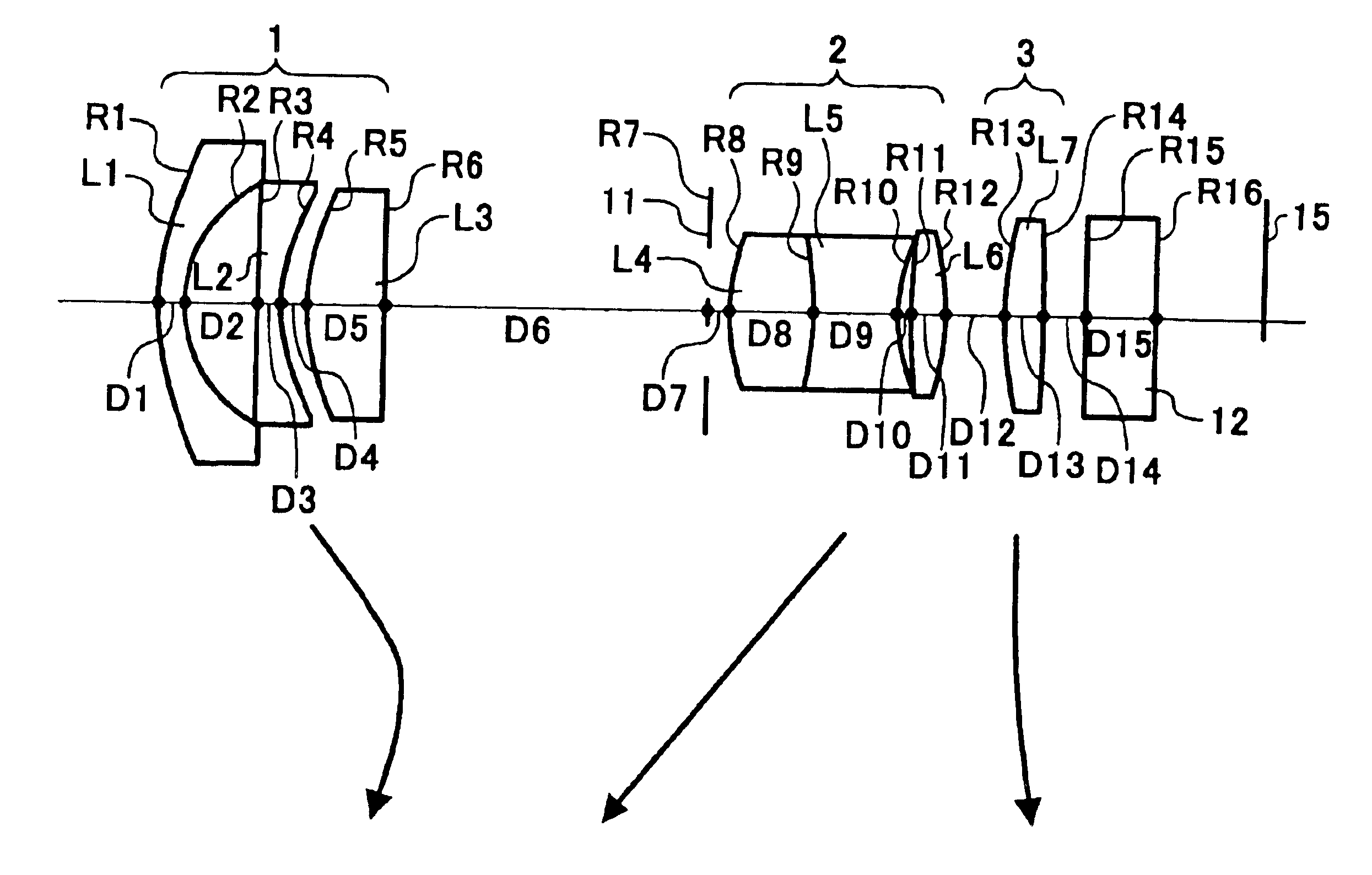
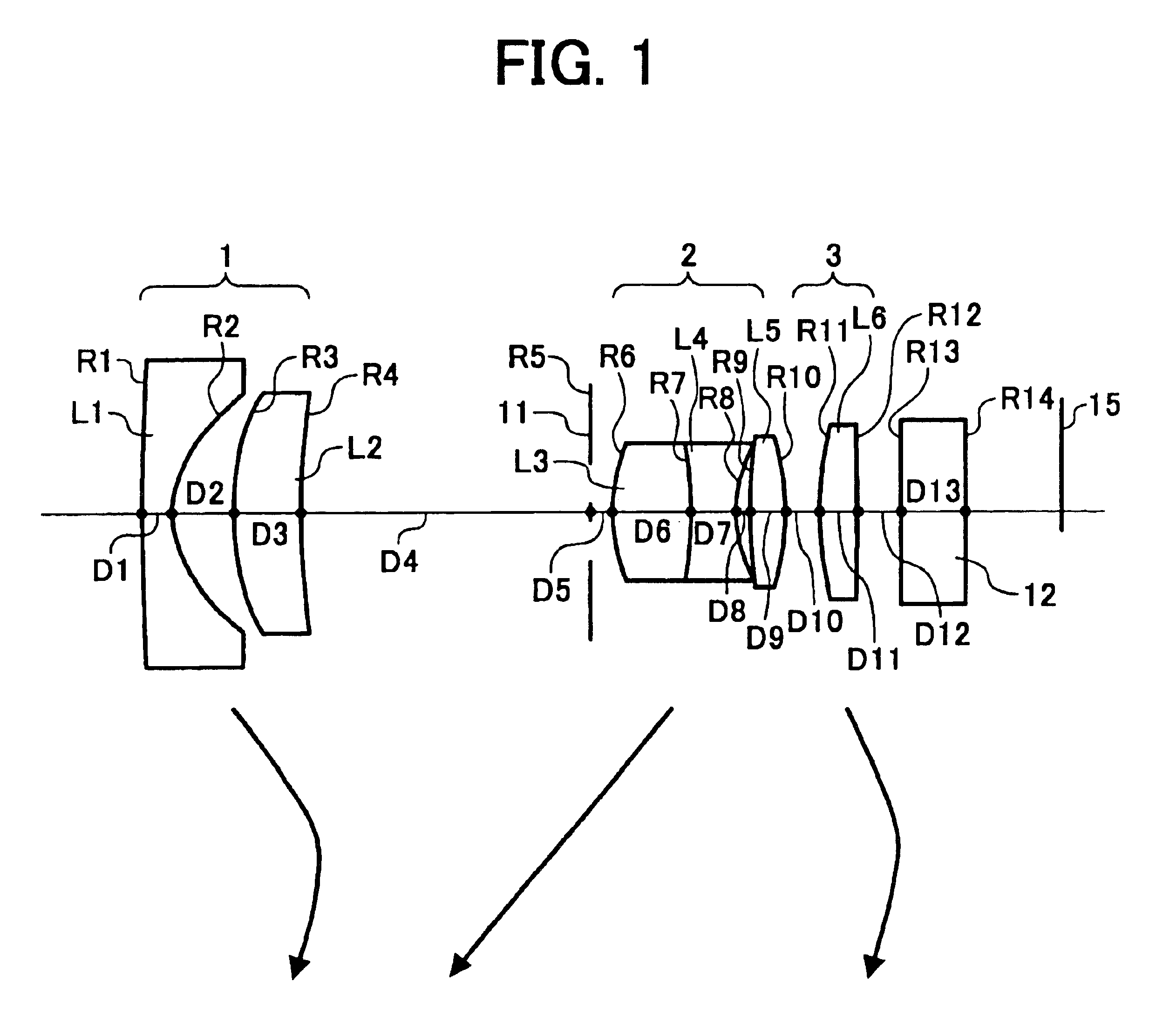
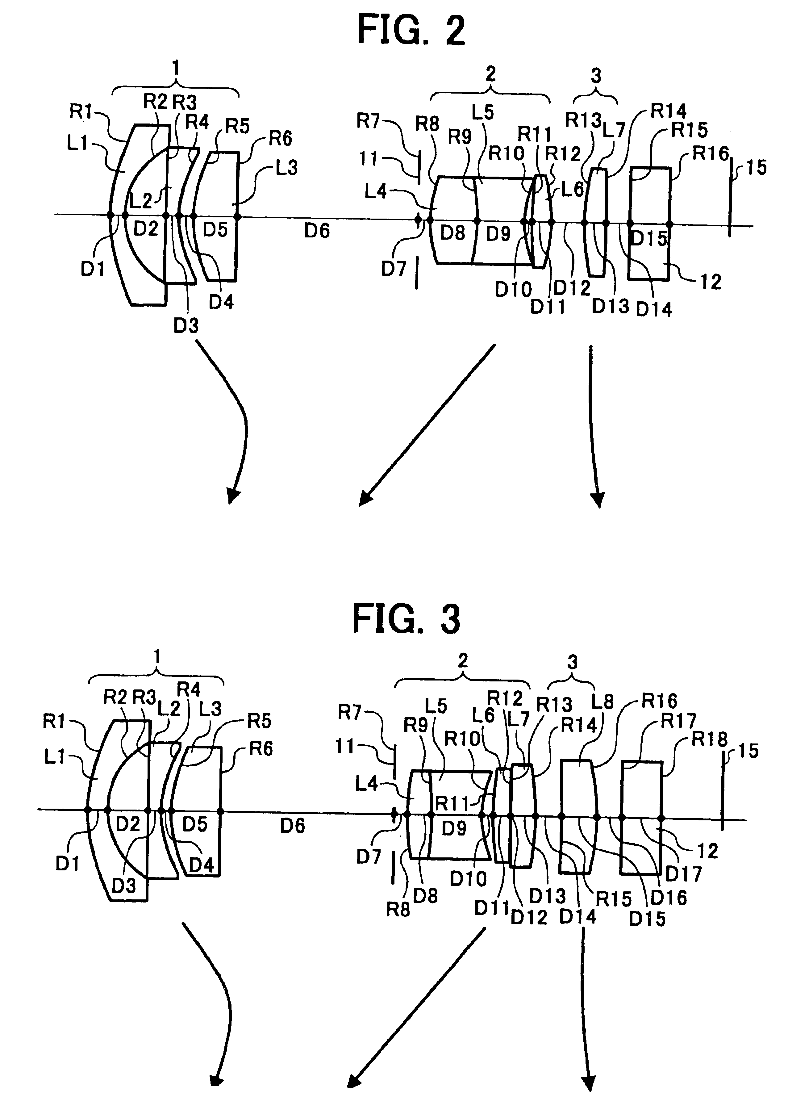
  • Zoom lens, and camera and portable information terminal for utilizing zoom lens
  • Zoom lens, and camera and portable information terminal for utilizing zoom lens
  • Zoom lens, and camera and portable information terminal for utilizing zoom lens

Examples


embodiment 6

FIG. 18 is an optical arrangement drawing showing EMBODIMENT 6 of the zoom lens according to the invention;

embodiment 7

FIG. 19 is an optical arrangement drawing showing EMBODIMENT 7 of the zoom lens according to the invention;

embodiment 8

FIG. 20 is an optical arrangement drawing showing EMBODIMENT 8 of a zoom lens according to the invention;

FIG. 21 is a view of an aberration curve at the end of the short focus of the zoom lens of EMBODIMENT 5;

FIG. 22 is a view of the aberration curve at the intermediate focal length of the zoom lens of EMBODIMENT 5;

FIG. 23 is a view of the aberration curve at the end of the long focus of the zoom lens of EMBODIMENT 5;

FIG. 24 is a view of an aberration curve at the end of the short focus of the zoom lens of EMBODIMENT 6;

FIG. 25 is a view of the aberration curve at the intermediate focal length of the zoom lens of EMBODIMENT 6;

FIG. 26 is a view of the aberration curve at the end of the long focus of the zoom lens of EMBODIMENT 6;

FIG. 27 is a view of an aberration curve at the end of the short focus of the zoom lens of EMBODIMENT 7;

FIG. 28 is a view of the aberration curve at the intermediate focal length of the zoom lens of EMBODIMENT 7;

FIG. 29 is a view of the aberration curve at the...


PUM


Abstract

A zoom lens comprising a first group of lenses (1) having negative focal length, a second group of lenses (2) having positive focal length, and a third group of lenses (3 having the positive focal length in order from an object side, in which the second group of lenses (2) moves monotonically from an image side to the object side and the first group of lenses 1 moves so as to correct shift in a position of an image surface, which is attended with a change in magnification, when the magnification is changed from an end of short focus to the end of long focus. The zoom lens is characterized in that the first group of lenses 1 has at least two lenses (L1) and (L2) and an air lens formed between the two lenses, both sides of the air lens are the aspheric surface, and the first group of lenses satisfies the following conditional expressions of no>1.50 and ni>1.60, where no indicates a refractive index to d line of the lens arranged on the object side in the air lens and ni indicates the refractive index to the d line of the lens arranged on the image side in the air lens.

Description

1. Field of the InventionThe present invention relates to a zoom lens which can be used in a digital camera, a video camera, a silver film camera, and the like and a camera and a portable information terminal which use the zoom lens.2. Description of the Prior ArtIn recent years, a digital camera is rapidly spread, and there are wide-ranging needs of users for the digital camera. In particular the user always desires high image quality and miniaturization, and high performance and the miniaturization are also desired for the zoom lens used as a taking lens.Though there are many ideas to use various kinds of zoom lenses for the digital camera, a type suitable for the miniaturization has a construction, in which a first group of lenses having negative focal length, a second group of lenses having positive focal length, and a third group of lenses having the positive focal length are provided in order from an object side, an iris moving integrally with the second group of lenses toward...

Claims


Application Information

Patent Timeline
Patent Type & Authority Patents(United States)
IPC IPC(8): G02B15/177G02B7/10
CPCG02B15/177G02B7/102G02B15/143507
Inventor OHASHI, KAZUYASUHIRAKAWA, MAKOTO
Owner RICOH KK
Why Eureka
Eureka Blog
Learn More