
Planar lens

a lens and planar technology, applied in the field of planar lenses, can solve the problems of deterioration in chemical resistance, difficult preparation of lens diameters less than 100 mm, glass has a drawback of poor chemical resistance,

Inactive Publication Date: 2004-11-09
NIPPON SHEET GLASS CO LTD
View PDF9 Cites 19 Cited by
  • Summary
  • Abstract
  • Description
  • Claims
  • Application Information

AI Technical Summary

Benefits of technology

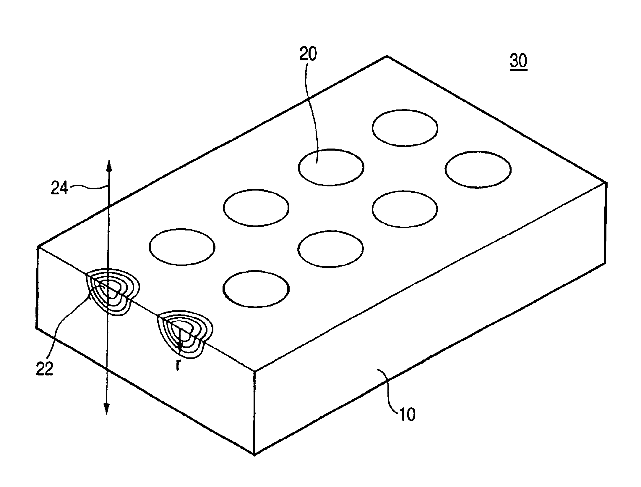
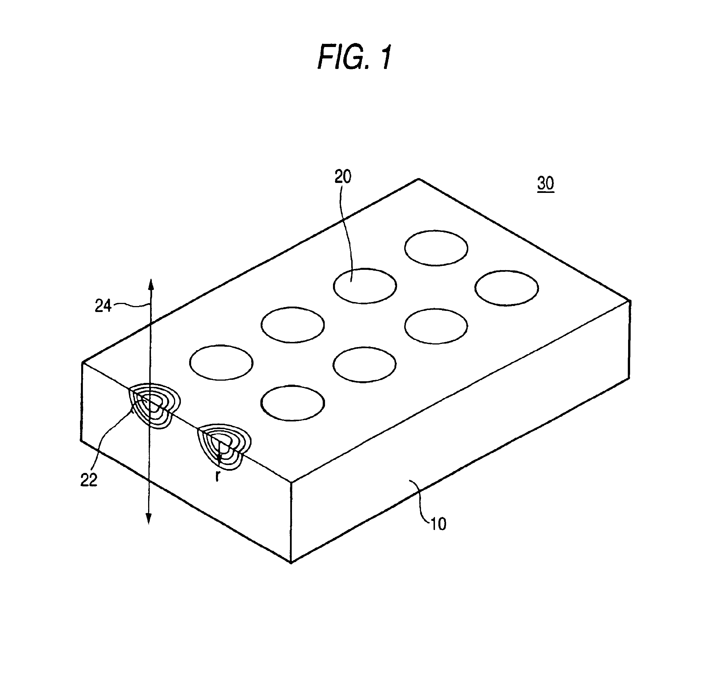
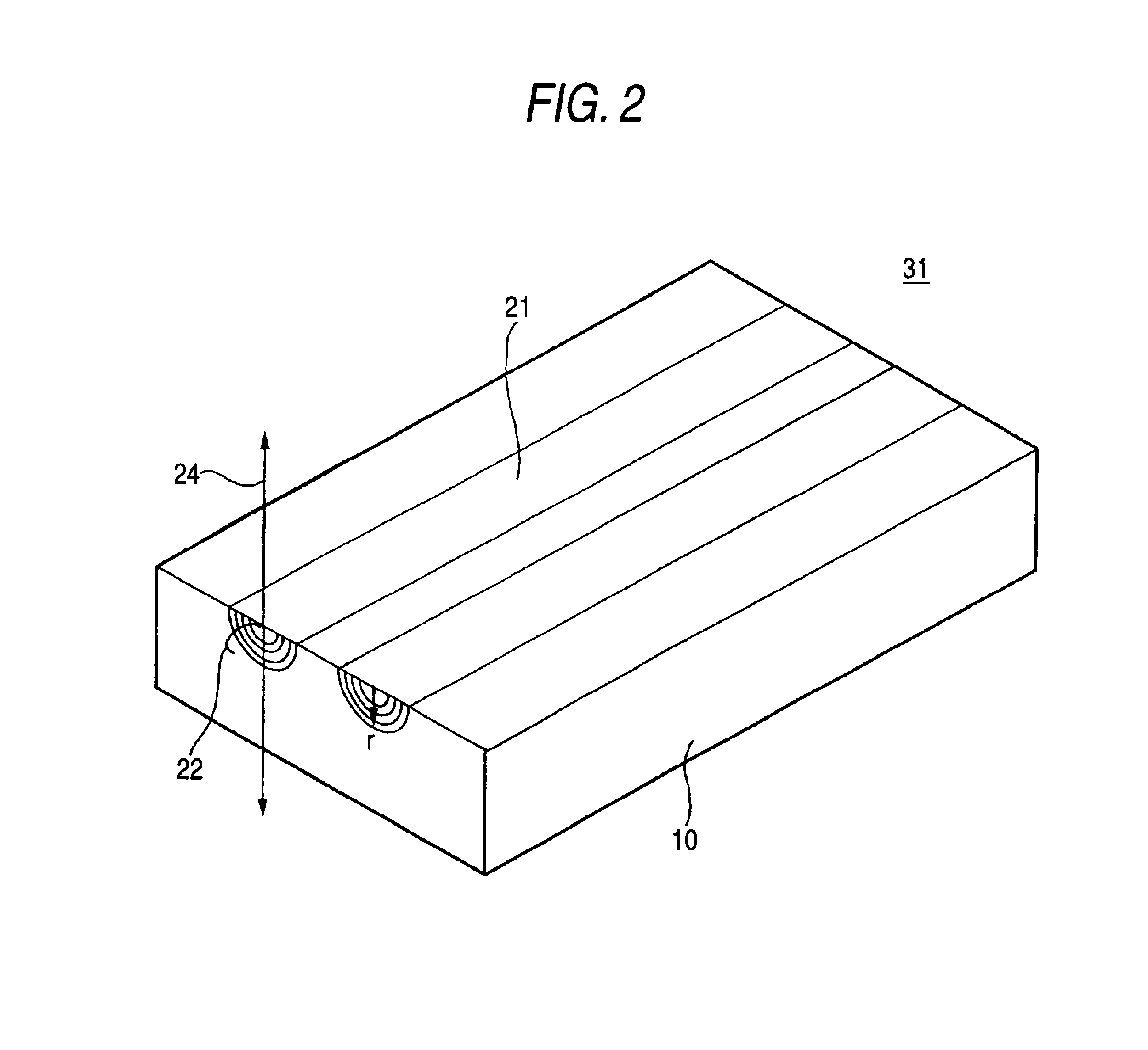
More specifically, the refractive index at some diffusion length is greater than that in a "linear" distribution, provided that the refractive index distribution curve is convex in the positive direction of the coordinate axis for the refractive index n within the distribution region of refractive indices of a planar lens. In other words, the refraction of light at the diffusion length satisfying the above condition becomes great and the focal length of the lens can be shortened. As a result, the numerical aperture of the lens can be enlarged. Additionally, the present planar lens is large in numerical aperture and sufficiently practicable as far as the numerical apertures thereof are of the order of 0.1.
Al.sub.2 O.sub.3 exerts an extremely great effect of enhancing the weathering resistance of glass. When the content of Al.sub.2 O.sub.3 exceeds 45%, Al.sub.2 O.sub.3 can easily become insoluble. Thus, it is necessary that the content of Al.sub.2 O.sub.3 fall within the range of not greater than 40%, preferably not greater than 32%, more preferably not greater than 25%.

Problems solved by technology

However, since the rate of diffusion of Tl ion in the glass substrate is small, it takes much time to prepare a lens having a diameter of not smaller than 100 .mu.m.
Therefore, such glass has a drawback of being poor in chemical resistance.
Therefore, the total amount of alkali metals required for attaining the desired lens performance is large, and thereby deterioration in chemical resistance is caused.
On the contrary, when the concentration of Li.sub.2 O exceeds 50%, devitrification occurs during cooling and solidification, making it impossible to form glass.
However, when the total concentration of alkaline metal oxides to be exchanged with Ag ion falls below 3%, the resulting lens has a small numerical aperture and thus is not practical.
On the contrary, when the total concentration of alkaline metal oxides to be exchanged with Ag ion exceeds 65%, the resulting glass shows a sudden deterioration of durability.
When the sum of concentration of the three components falls below 25%, the resulting glass exhibits deteriorated durability and stability.
On the contrary, when the sum of concentration of the three components exceeds 85%, the resulting glass exhibits a raised melting temperature and a required amount of other constituents cannot be secured, making it impossible to obtain a lens having a great difference of refractive index.
When the concentration of this component exceeds 85%, the resulting glass exhibits a raised melting temperature and a required amount of other constituents cannot be secured, making it impossible to obtain a lens having a great difference of refractive index.
When the concentration of this component exceeds 85%, the resulting glass exhibits deteriorated durability and stability.
However, when the content of MgO exceeds 35%, the viscosity of the resulting molten glass is lowered more than required, causing devitrification during cooling and solidification and hence making it impossible to form glass.
However, when these components are used in amounts greater than the above defined range, ion exchange can difficultly proceed smoothly.

Method used


Image

  • Planar lens
  • Planar lens
  • Planar lens

Examples


example 1

A planar lens was produced using a substrate having the mother glass composition shown on the Example 1 column of Table 1 and performing ion exchange treatment under the foregoing condition. The planar lens thus produced was examined for refractive index distribution by use of light with a wavelength of 546 nm, and the result obtained is shown in FIG. 9. As illustrated therein, the n-r curve in Example 1 has proved to be clearly "upwardly convex" in shape. Further, n.sub.2 / n.sub.1 was found to be 1.029 greater than 1. Additionally, the shape of this n-r curve corresponds to FIG. 5C.

On the other hand, the concentration distribution of Ag was measured by EPMA. And the results thereof are shown in FIG. 10. As can be seen therefrom, the a-r curve also had a clearly "upwardly convex" shape, and a.sub.2 / a.sub.1 was found to be 4.61 greater than 1.

From a comparison of the n-r curve shown in FIG. 9 and the a-r curve shown in FIG. 10, it can be seen that the refractive index distribution a...

examples 2 to 13

Table 1 also shows the composition and a.sub.2 / a.sub.1 ratio of Examples 2 to 13. All the samples show a.sub.2 / a.sub.1 ratio of greater than 1.0, which means that the distribution curve is upwardly convex.

On the other hand, a-r curve of Example 11 has an a.sub.2 / a.sub.1 ratio as small as 1.60, which means a small upwardly convex degree, as compared with Example 1 (FIG. 10) as shown in FIG. 11. In this case, the numerical aperture is 0.08, which is greater than the expected value (0.05) in the linear distribution of refractive indices but smaller than that of Examples 1 and 2.

example 14

While all the samples of Examples 1 to 13 comprise SiO.sub.2 diffused therein as a main component, the present example provides an example of glass containing B.sub.2 O.sub.3 and LiO.sub.2 in almost the same concentration besides SiO.sub.2. In this case, a.sub.2 / a.sub.1 ratio is as great as 2.5, which means that the distribution curve is convex.


PUM

PropertyMeasurementUnit
mol %aaaaaaaaaa
diameteraaaaaaaaaa
diameteraaaaaaaaaa

Abstract

The planar lens of the invention having a flat glass substrate, in which a refractive index distribution is formed by diffusing a refractive index-increasing component into the flat glass substrate in a substantially hemispherical form or semicylinder form, wherein the refractive index-increasing component is silver, and the flat glass substrate comprises Li as an alkali metal that is subject to an ion exchange with the silver.

Description

The present invention relates to a planar lens for use in the art of optical communication, optical data processing, etc., and a production method thereof.DESCRIPTION OF THE RELATED ARTTo cope with the rise in capacity of communications or the rise in the amount of data to be processed in data processing, the utilization of parallelism of light has been noted as an extremely effective means. In order to utilize parallelism of light, it is desired that optical fibers, which are optical transmission means, be arranged in arrays, not to mention light source and optical detector. It is necessary that lenses, which are light coupling means, be arrayed as well.A planar lens array having many fine lens formed in a transparent flat substrate has excellent characteristics of arrayed lens. Since such a planar lens array is prepared by photolithography, a fine lens having a diameter of not greater than 1 mm can be easily prepared. Further, these lenses can be arrayed with a high precision. Acc...

Claims


Application Information

Patent Timeline
Patent Type & Authority Patents(United States)
IPC IPC(8): G02B3/00
CPCC03C3/076C03C3/083C03C3/089C03C3/091C03C3/095C03C3/097G02B3/0087C03C3/19C03C21/002C03C21/005G02B3/0012G02B3/005G02B3/0056C03C3/14
Inventor TSUDA, MASAHIROYOSHII, SHIGEKAZUSAKAGUCHI, KOICHI
Owner NIPPON SHEET GLASS CO LTD
Learn More