
Filter made of porous ceramic sintered body

a technology of porous ceramic and sintered body, which is applied in the direction of machines/engines, chemical/physical processes, domestic applications, etc., can solve the problems of increasing pressure loss, inevitably required adjustment, and the inability to produce any kind of filter having any average pore diameter and any distribution of pore diameter according to various kinds of uses

Inactive Publication Date: 2004-10-05
NGK INSULATORS LTD
View PDF18 Cites 36 Cited by
  • Summary
  • Abstract
  • Description
  • Claims
  • Application Information

AI Technical Summary

Benefits of technology

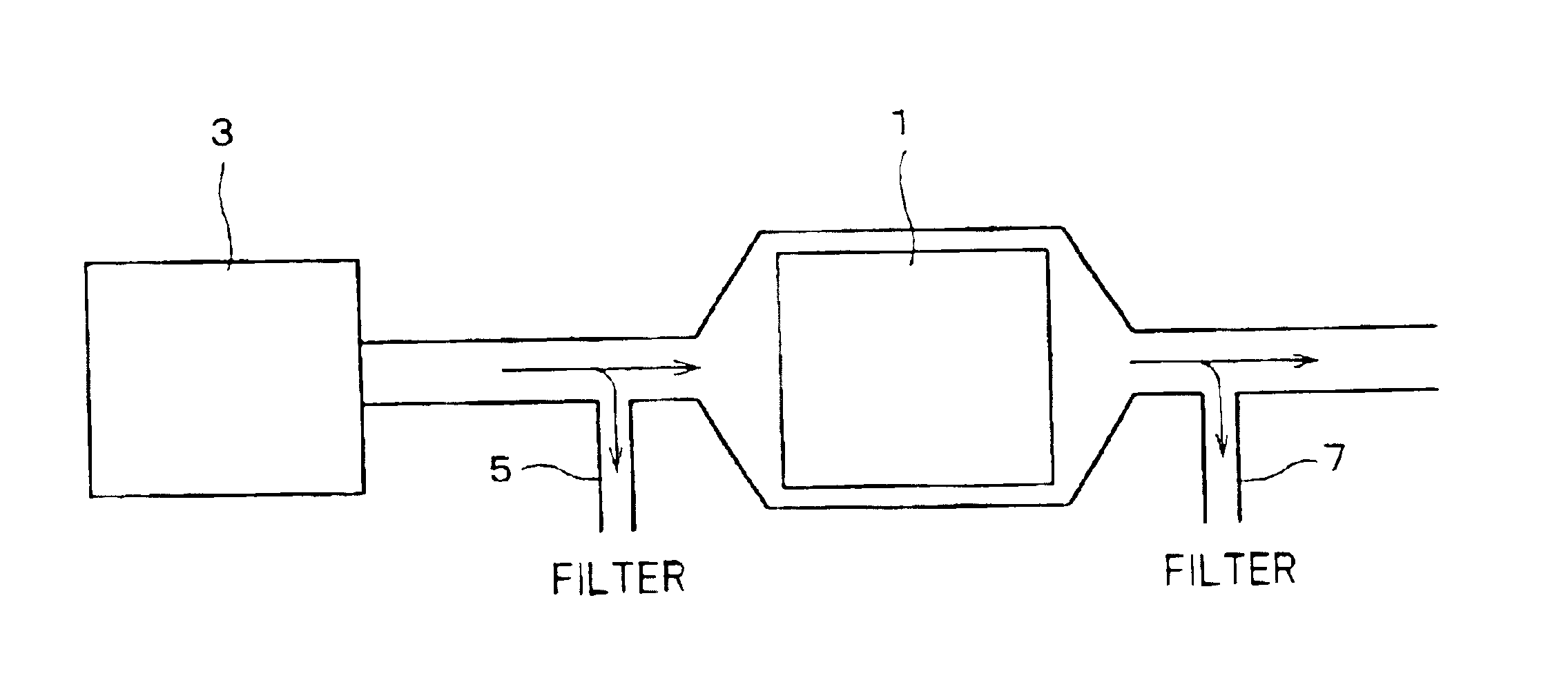
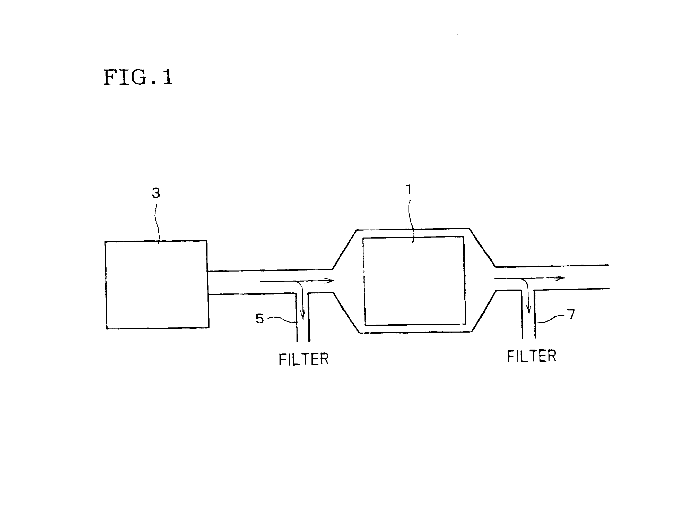
The present invention provides a filter made of a porous ceramic sintered body that can be easily adjusted to different uses without changing the material properties of the filter. The filter has a honeycomb structure with large number of through channels partitioned by partition walls. The pore size of the filter is important for its scavenging efficiency and pressure loss. The invention provides filters with appropriate pore size distribution to achieve both high scavenging efficiency and low pressure loss. The technique of the invention allows for a relatively easy and flexible adjustment of the filter design by balancing the prevention of particulate passage and suppression of pressure loss. This filter design can be used for various applications without changing the material properties of the filter.

Problems solved by technology

On the other hand, if the diameter of its fine pores become smaller, the pressure loss increases.
However, as shown in JP-A-5-23512, it is necessary to change qualities of materials, raw materials, a production method, and the like, of a filter from the foundation, thereby adjustment is inevitably required.
In addition, there is a problem that it is impossible to produce any kind of filter having any average pore diameter and any distribution of pore diameter according to various kinds of uses, depending upon kinds of particulates, temperature for use, or the like.
As described above, if there are many large fine pores in the filter, a part of the particulates, which are scavenging targets, pass through the partition wall without being captured by the partition wall and are discharged, and as a result, the reduction in the scavenging efficiency is brought about.
On the contrary, a problem that a pressure loss increases as small fine pores increases is caused.

Method used


Image

  • Filter made of porous ceramic sintered body
  • Filter made of porous ceramic sintered body

Examples


Embodiment Construction

The present invention is described in more detail on the basis of Examples. However, the present invention is by no means limited to these Examples.

(Manufacture of Filter)

There were manufactured DPFs of cordierite and DPFs of SiC having a columnar shape of an outside shape having a diameter of 150 mm, a length of 150 mm, and various kinds of thickness of partition walls as shown in Tables 2 and 3. Thickness of the partition wall was varied by substituting nozzles used for a honeycomb extrusion molding. Thus produced cordierite DPFs and SiC DPFs were measured for a distribution of pore diameters (a diameter) and an average pore diameter (a diameter) by a method of mercury penetration, and results as in Table 1 could be obtained. As for DPFs of the same materials, because the same manufacturing method and the same raw material were employed even if a thickness of the partition wall is different from one another, the similar distribution of pore diameters and average pore diameter were...


PUM

PropertyMeasurementUnit
diameteraaaaaaaaaa
diameteraaaaaaaaaa
porosityaaaaaaaaaa

Abstract

The invention is directed to a filter made of a porous ceramics sintered body has a honeycomb structure having a large number of through channels partitioned by partition walls and passing through along an axial direction. When a ratio of a pore volume having a diameter of 30 mum or more to a total pore volume, measured by a method of mercury penetration, of the filter is P1(%) and a thickness of said partition wall is T (mum), these satisfy the relationship defined by the following formula: P1x10<=T. In case of this filter, one may produce it relatively easily on a large scale without adjustment requiring the change of the properties of material for a filter, and the filter can flexibly cope with various uses.

Description

BACKGROUND OF THE INVENTION AND RELATED ART STATEMENTThe present invention relates to a filter made of a porous ceramic sintered body to scavenge particulates (fine particles) in fluid, which is represented by a diesel particulate filter.The diesel particulate filter (DPF), which is a kind of filter of a porous ceramic sintered body, has a honeycomb structure having a large number of through channels (cells) partitioned by partition walls (libs) and passing through along an axial direction, and adjacent through channels are alternatively sealed at the opposite end mutually so that both end surfaces of the filter are clogged checkerwise.When exhaust gas of a diesel engine is sent from one end surface of this honeycomb structure, exhaust gas containing particulates flows inside from the through channels which are not sealed in an end portion of the end surface, passes through the porous partition walls, and enters into the other through channels which are not sealed in the other end p...

Claims


Application Information

Patent Timeline
Patent Type & Authority Patents(United States)
IPC IPC(8): B01D39/20F01N3/022B01D46/24C04B38/00
CPCB01D39/2075B01D46/2474F01N3/0222B01D46/2429Y10S55/30B01D46/2466B01D2046/2433B01D2046/2437B01D2046/2496B01D2275/30B01D2279/30F01N2330/06F01N2330/14F01N2530/24Y02T10/20Y02T10/12B01D46/24492B01D46/24491B01D46/2498B01D46/2482
Inventor NODA, NAOMI
Owner NGK INSULATORS LTD
Learn More