
Magnetic tape cartridge

a technology of magnetic tape and cartridge, which is applied in the field of magnetic tape cartridge, can solve the problems of difficult automation of the product line requiring thousands of man-hours, and affecting the efficiency of the magnetic tape cartridg

Inactive Publication Date: 2004-09-28
FUJIFILM CORP +1
View PDF2 Cites 3 Cited by
  • Summary
  • Abstract
  • Description
  • Claims
  • Application Information

AI Technical Summary

Problems solved by technology

In the assembling of the spring member and the slide door, consequently, thousands of man-hours are required, and the automatization of the product line of a magnetic tape cartridge had been made difficult.
As a result of this disturbance, the automatization of the product line of the magnetic tape cartridge becomes difficult.

Method used


Image

  • Magnetic tape cartridge
  • Magnetic tape cartridge
  • Magnetic tape cartridge

Examples


second preferred embodiment

The explanation about the second preferred embodiment of the magnetic tape cartridge according to the present invention will be carried out as below. In the following explanation, the components same as explained in the first preferred embodiment is indicated by the same symbols and the explanation thereof is omitted.

As shown in FIG. 5, a hooking part 26b is formed on the rib 26 of the lower half 2, so as to be prolonged to the almost mid position in the height direction of the rib 26.

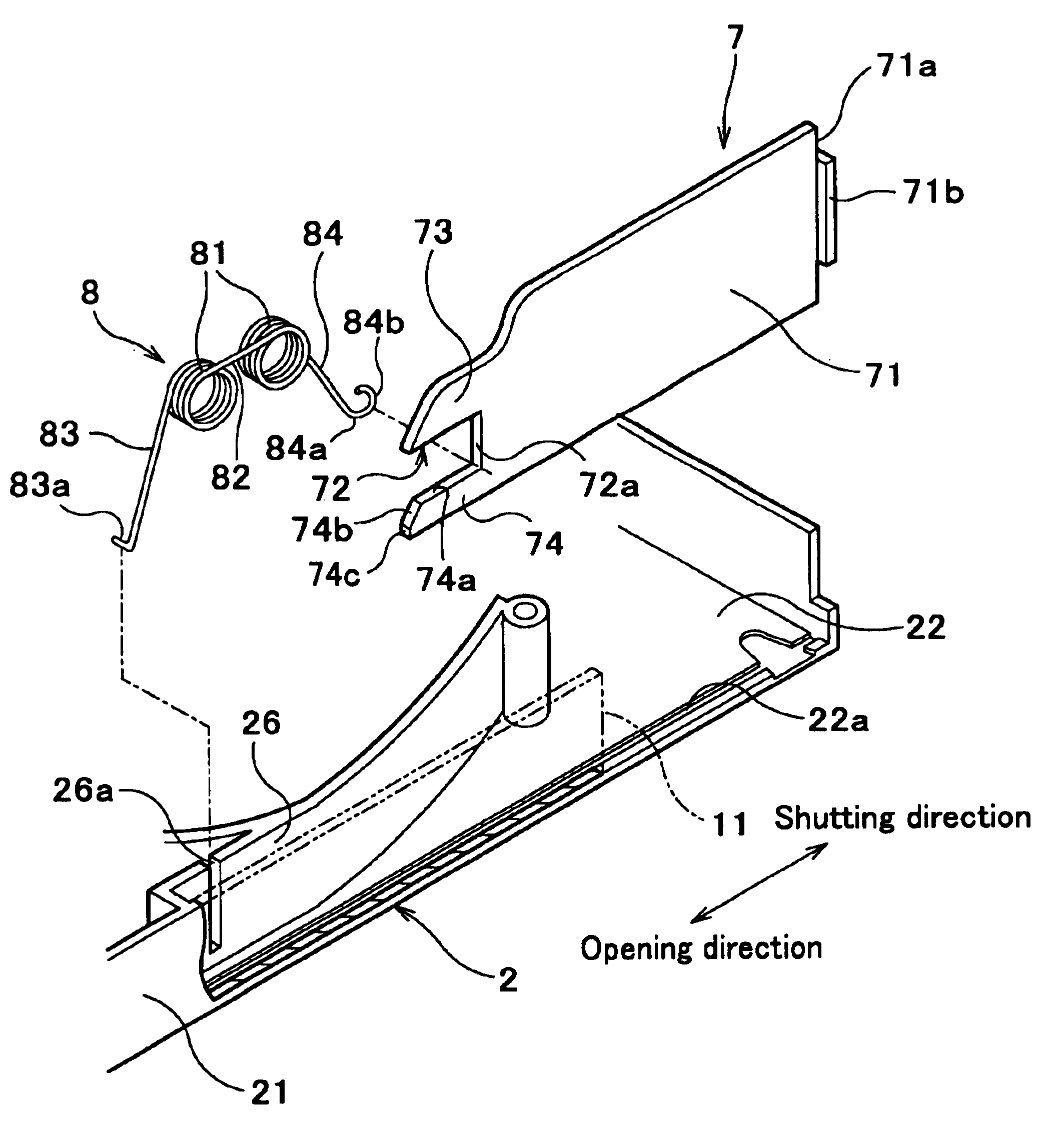
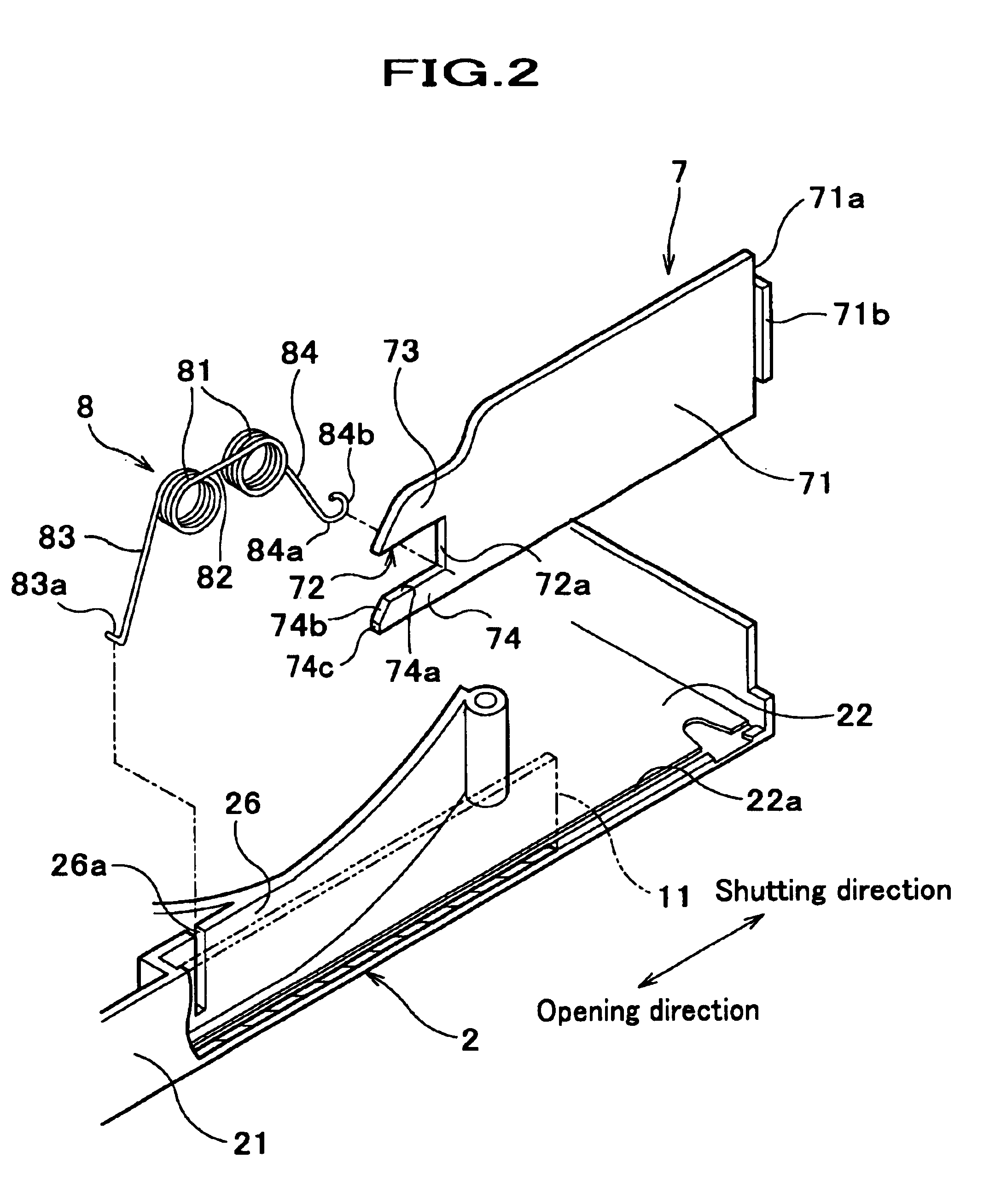
A slide door 7' is a plate having the same thickness as the width of the guide groove 22a. The size of the slide door 7' at the shutting direction side is established so as to cover the opening 11 formed on the side wall 21. At the opening direction side of the slide door 7' is caved so as not to interfere with the spring member 8.

A hooking hole 7a' for connecting with the spring member 8 is bored at the vicinity of the bottom in the opening direction side of the slide door 7'. The position of the hook...

third preferred embodiment

The explanation about the third preferred embodiment of the magnetic tape cartridge according to the present invention will be carried out as below. In the following explanation, the components same as explained in the first preferred embodiment is indicated by the same symbols and the explanation thereof is omitted.

As shown in FIG. 8, a flection part 83b (a supported part, pressed means) is formed at opening direction side of the spring arm 83 of the spring member 8. This flection part 83b is formed by bending the spring arm 83 upwardly at the tip part side and further bending downwardly at it's tip end.

As shown in FIG. 9, the upper half 3 is a case made of the same resin as the lower half 2, and a side wall 31 having an opening 11, a rib 33 for reinforcing, and the like are provided thereto. The position, the side wall 31 and the rib 33 are established, is determined so as to be agreed with the side wall 21 and the rib 26 of the lower half without play, when the upper half and the...


PUM

PropertyMeasurementUnit
magneticaaaaaaaaaa
shapeaaaaaaaaaa
timeaaaaaaaaaa

Abstract

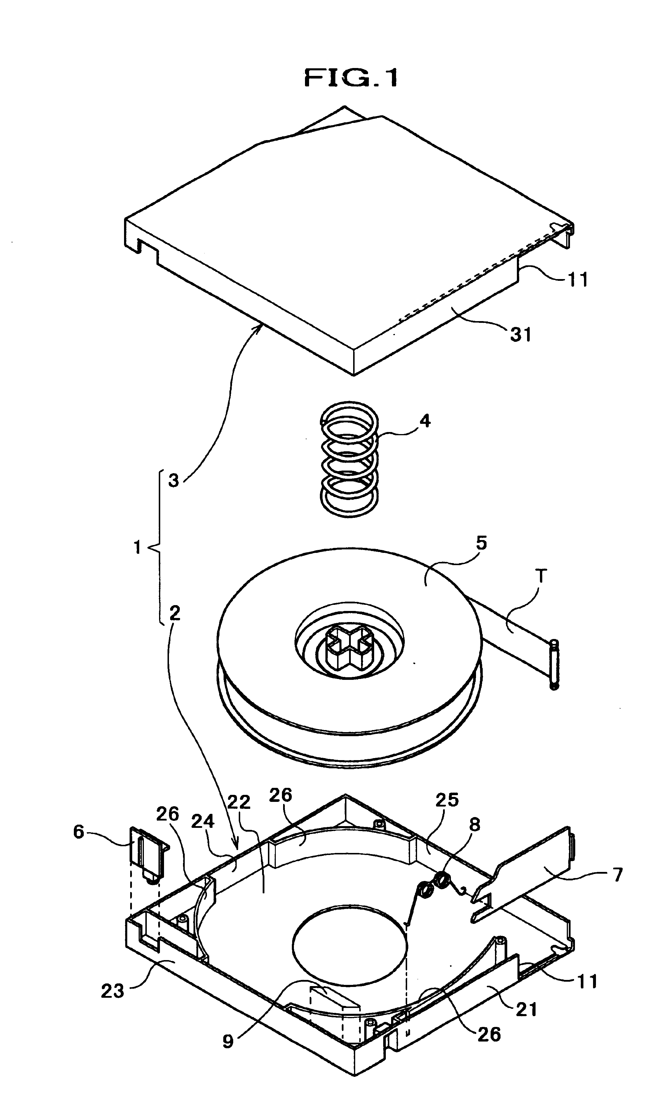
A magnetic tape cartridge, which can be assembled using an automated products line by enabling the assembling operation of a spring member and a slide door with ease. For attaining these problems, there is provided a magnetic tape cartridge comprising a magnetic tape cartridge comprising; an opening provided on one side wall of a cartridge case, and is used for tape drawing; a slide door slidably supported by a guide part disposed along said one side wall, and said slide door is used achieving the shutting-and-opening operation of said opening; spring member for impelling said slide door to the shutting direction side, and tape drawing; placed on said guide part; and a leading part for leading one end part of said spring member to a spring engaging part provided on said slide door, and is provided at one end part of said spring member.

Description

1. Field of the InventionThe present invention relates to a magnetic tape cartridge, in which a single reel, a magnetic tape is wound thereon, is rotatably stored, and is composed of an upper half, a lower half, an opening for drawing the magnetic tape, and a slide door for achieving the opening-and-shutting of the opening. More specifically, the present invention relates to a spring member, which impels a slide door to the shutting direction for shutting the opening of the magnetic tape cartridge.2. Description of the Related ArtIn the magnetic tape cartridge used as the external recording medium for recording the back up data of a computer etc, a single reel, a magnetic tape is to be wound, is rotatably stored within a cartridge case. This cartridge case is composed of an upper half and a lower half, and has a nearly flat square shape.In the occasion of using, a magnetic tape is drawn out from the cartridge case, and is wound by the reel mounted on a read-write apparatus. Thus the...

Claims


Application Information

Patent Timeline
Patent Type & Authority Patents(United States)
IPC IPC(8): G11B23/107G11B23/113G11B23/04G11B23/08
CPCG11B23/045G11B23/107G11B23/113
Inventor KITAMURA, KOUTASHIGA, HIDEAKIYAMAMOTO, HIDETOSHI
Owner FUJIFILM CORP
Learn More