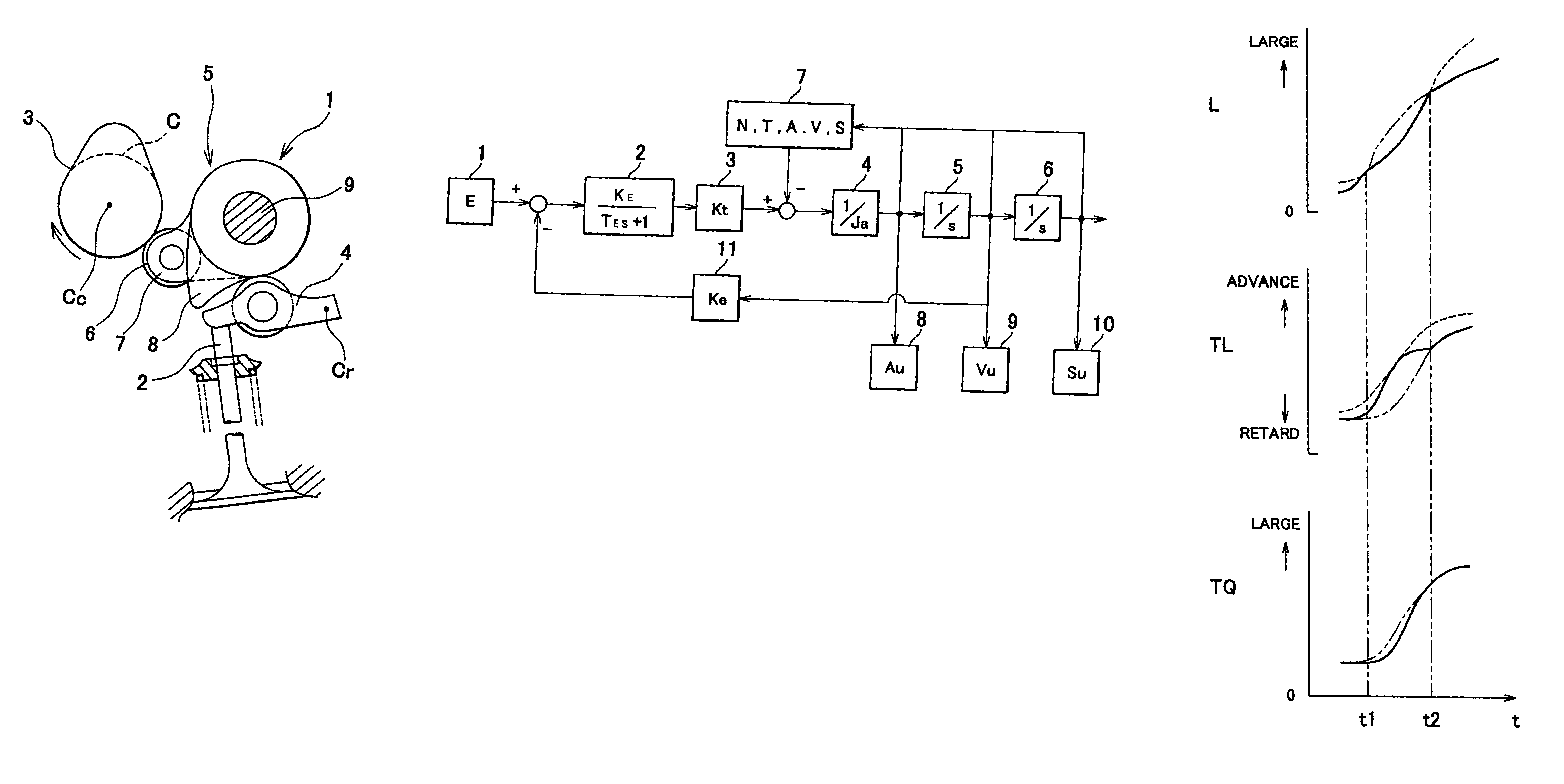

Control apparatus and method for valve actuating system of internal combustion engine

a technology of control apparatus and internal combustion engine, which is applied in the direction of electrical control, machines/engines, non-mechanical valves, etc., can solve the problem that the lift characteristics of the intake valve may not be changed as desired

Inactive Publication Date: 2004-08-31
TOYOTA JIDOSHA KK
View PDF6 Cites 12 Cited by
  • Summary
  • Abstract
  • Description
  • Claims
  • Application Information

AI Technical Summary

Benefits of technology

The invention relates to a control apparatus and method for a valve actuating system of an internal combustion engine. The system includes a lift characteristic changing mechanism for changing the lift characteristics of the intake valves or exhaust valves of the engine. The control apparatus calculates a target operation value for the lift characteristic changing mechanism based on a controlled variable and at least one parameter related to the environment surrounding the mechanism. The control apparatus controls the lift characteristic changing mechanism within the realized range of the operation value. The invention provides a control apparatus and method that can accurately control the lift characteristics of the valves, regardless of changes in the environment or the output torque of the electric motor driving the mechanism.

Problems solved by technology

Where the output torque of the electric motor is reduced, the lift characteristics of the intake valves may not be changed as desired even if the lift characteristic changing mechanism is driven by the electric motor.
The above-described problem occurs not only to the valve actuating system provided with the lift characteristic changing mechanism for changing the lift characteristics of the intake valves, but also to a valve actuating system for lifting exhaust valves of the engine, which system is provided with a lift characteristic changing mechanism for changing lift characteristics of the exhaust valves.

Method used


Image

  • Control apparatus and method for valve actuating system of internal combustion engine
  • Control apparatus and method for valve actuating system of internal combustion engine
  • Control apparatus and method for valve actuating system of internal combustion engine

Examples


first embodiment

Thus, according to the invention, the target operation values of the electric motor 16 are determined, taking account of the realizable operation ranges of the motor 16 obtained from the level of voltage (controlled variable) that can be applied to the motor 16 and the environment surrounding the motor 16, which influence the output characteristics of the electric motor 16. With this arrangement, even if the level of voltage (controlled variable) that can be applied to the electric motor 16 and / or the environment surrounding the motor 16 changes, the lift amount of the intake valve 2 can be changed as desired, and the required characteristics of the engine can be kept in the neighborhood of the optimum characteristics.

Namely, according to the first embodiment of the invention, the target operation values of the lift amount changing mechanism are determined, taking account of the realizable operation ranges of the lift amount changing mechanism obtained from the controlled variable t...

second embodiment

Thus, according to the invention, the target operation values of the hydraulic pump 27 are determined, taking account of the realizable operation ranges of the hydraulic pump 27 obtained from the driving force (controlled variable) that can be applied to the hydraulic pump 27 and the environment surrounding the hydraulic pump 27, which influence the output characteristics of the hydraulic pump 27. With this arrangement, even if the driving force (controlled variable) that can be applied to the hydraulic pump 27 or the environment surrounding the hydraulic pump 27 changes, the lift timing of the intake valves 2 is changed as desired, and consequently the required characteristics of the internal combustion engine can be kept in the neighborhood of the optimum characteristics.

Namely, according to the second embodiment of the invention, the target operation values of the lift timing changing mechanism are determined, taking account of the realizable operation ranges of the lift timing c...

third embodiment

Needless to say, in the third embodiment, if the initially calculated target operation values of one of the electric motor 16 and the hydraulic pump 27 are not within the corresponding realizable operation ranges, the target operation values of the hydraulic pump 27 may be changed so as to approach the realizable operation values, and target operation values of the electric motor 16 may be newly calculated to be within the realizable operation ranges of the electric motor 16, based on the thus changed target operation values of the hydraulic pump 27, so that the required characteristics of the engine become as close to the optimum characteristics as possible, or so that the required characteristics of the engine to which priorities are assigned become as close to the optimum characteristics as possible in order of priority.

Also, if the initially calculated target operation values of one of the electric motor 16 and the hydraulic pump 27 are not within the corresponding realizable op...


PUM


Abstract

A control apparatus is provided for a valve actuating system which is operable to lift an intake valve or an exhaust valve of an internal combustion engine and includes a lift characteristic changing mechanism for changing a lift characteristic of the intake valve or the exhaust valve. The control apparatus calculates a target operation value of the lift characteristic changing mechanism, and calculates a realizable range of the operation value which can be realized by the lift characteristic changing mechanism, based on a controlled variable that can be given to the lift characteristic changing mechanism and at least one parameter related to an environment surrounding the lift characteristic changing mechanism. If the target operation value is not within the realizable range of the operation value, the control apparatus calculates a new target operation value to be within the realizable range.

Description

INCORPORATION BY REFERENCEThe disclosure of Japanese Patent Application No. 2002-253999 filed on Aug. 30, 2002, including the specification, drawings and abstract, is incorporated herein by reference in its entirety.1. Field of the InventionThe invention relates to control apparatus and method for a variable valve actuating system of an internal combustion engine.2. Description of Related ArtFor example, U.S. Pat. No. 6,401,675 B1 discloses a valve actuating system for lifting intake valves of an internal combustion engine, which system is provided with a lift characteristic changing mechanism for changing lift characteristics of the intake valves. The lift characteristic changing mechanism disclosed in the above-identified U.S. Patent is arranged to be driven by an electric motor.In the valve actuating system as described above, characteristics or tendencies of changes in the lift characteristics of the intake valves effected by the lift characteristic changing mechanism change dep...

Claims


Application Information

Patent Timeline
Patent Type & Authority Patents(United States)
IPC IPC(8): F01L1/26F01L13/00F01L1/34F02D13/02
CPCF01L1/267F01L13/0063F02D13/0211F01L1/3442F01L2201/00F02B2075/125F02D2041/001F02D2041/1433Y02T10/18Y02T10/12
Inventor KANAMARU, MASANOBUFUWA, NAOHIDEEIRAKU, AKIRAKINOSHITA, GOHKIHAKARIYA, MASASHIYAMANASHI, TAKAHIRO
Owner TOYOTA JIDOSHA KK
Learn More