
Collapsible frame

a frame and collapsible technology, applied in the field of collapsible frames, can solve the problems of unstable frame, heavy prior art frame weight, cumbersome assembly and disassembly, complex articulated linkage, etc., and achieve the effect of simple structure, quick and easy raising and lowering

Inactive Publication Date: 2004-08-10
PRICE ROY JUSTIN
View PDF34 Cites 82 Cited by
  • Summary
  • Abstract
  • Description
  • Claims
  • Application Information

AI Technical Summary

Benefits of technology

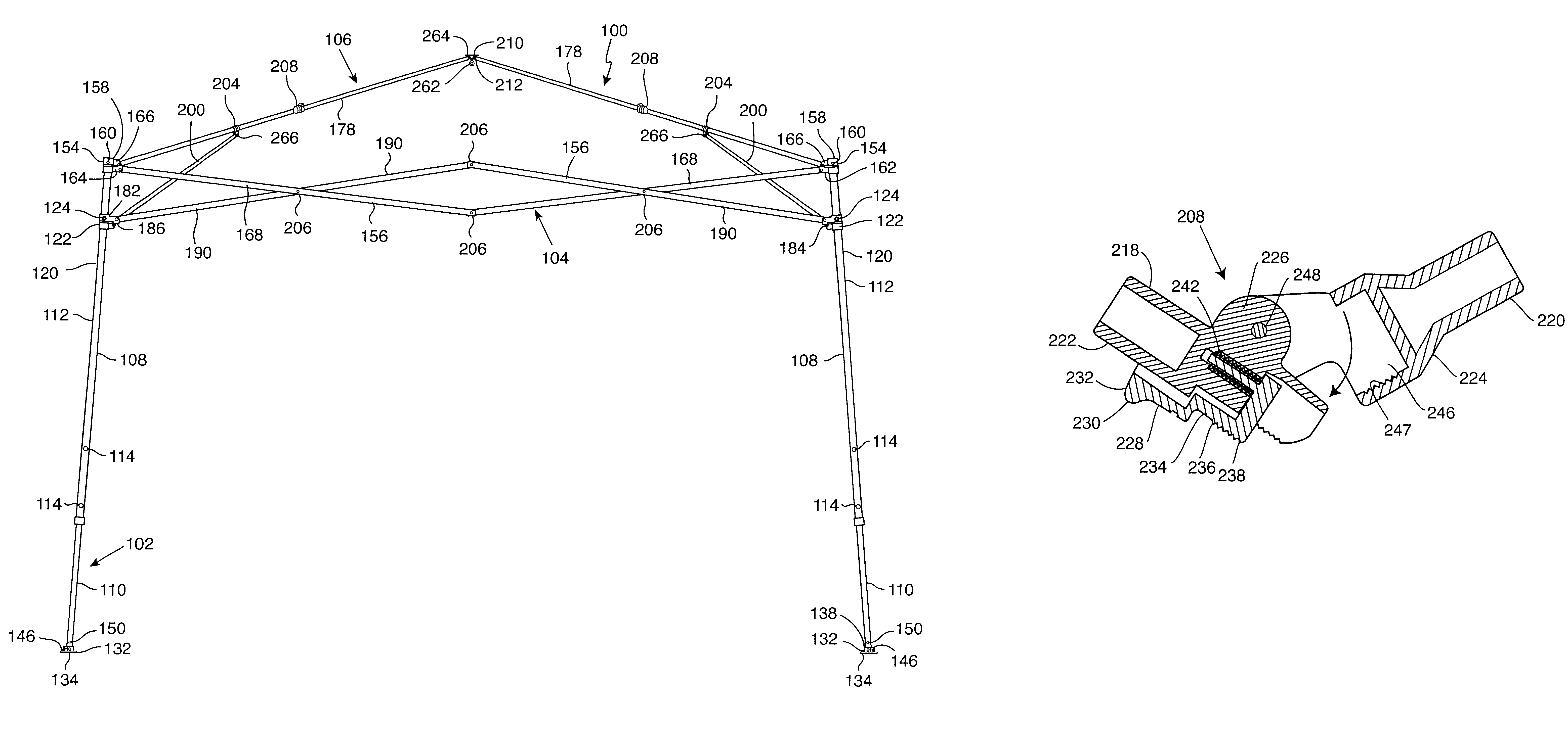
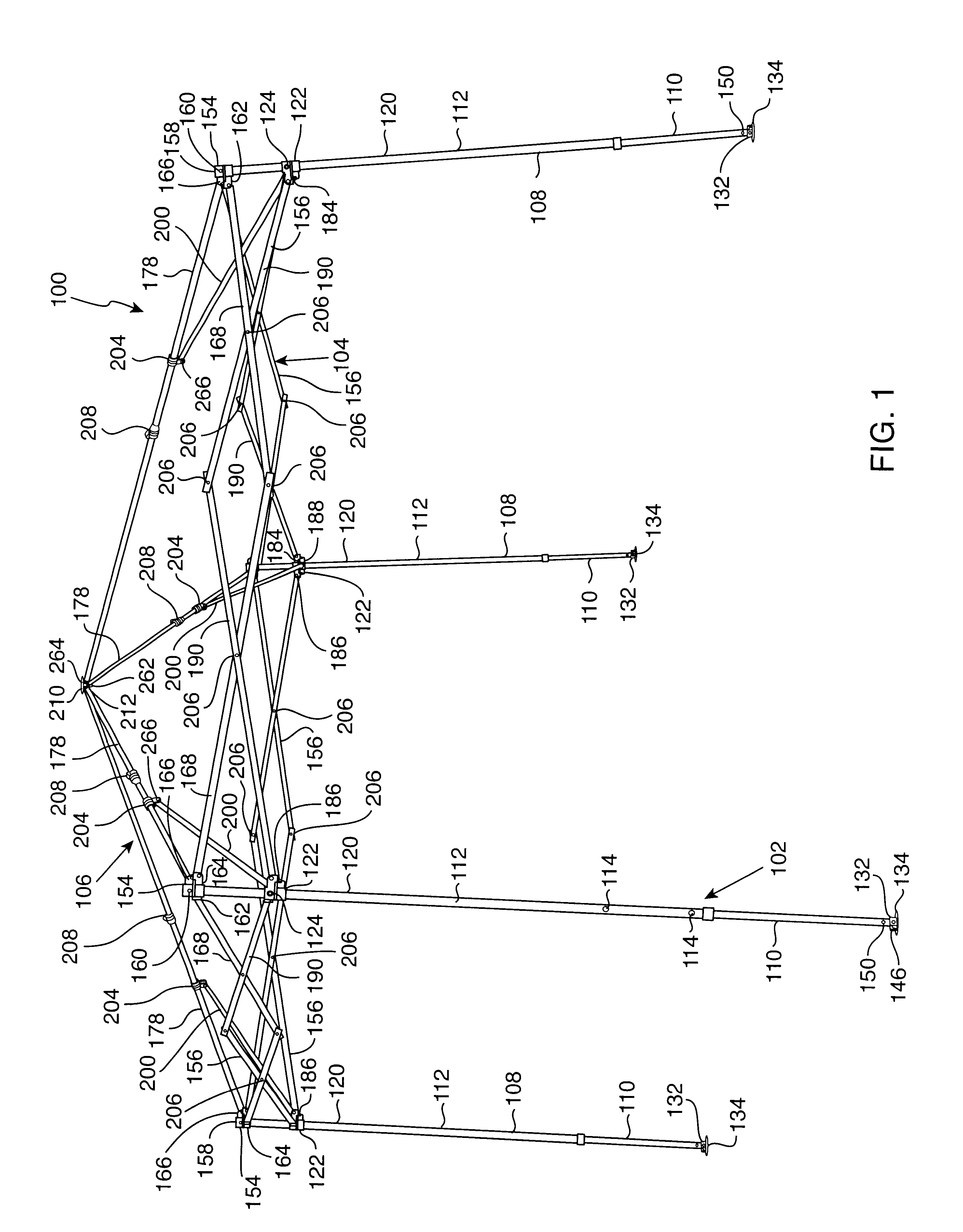
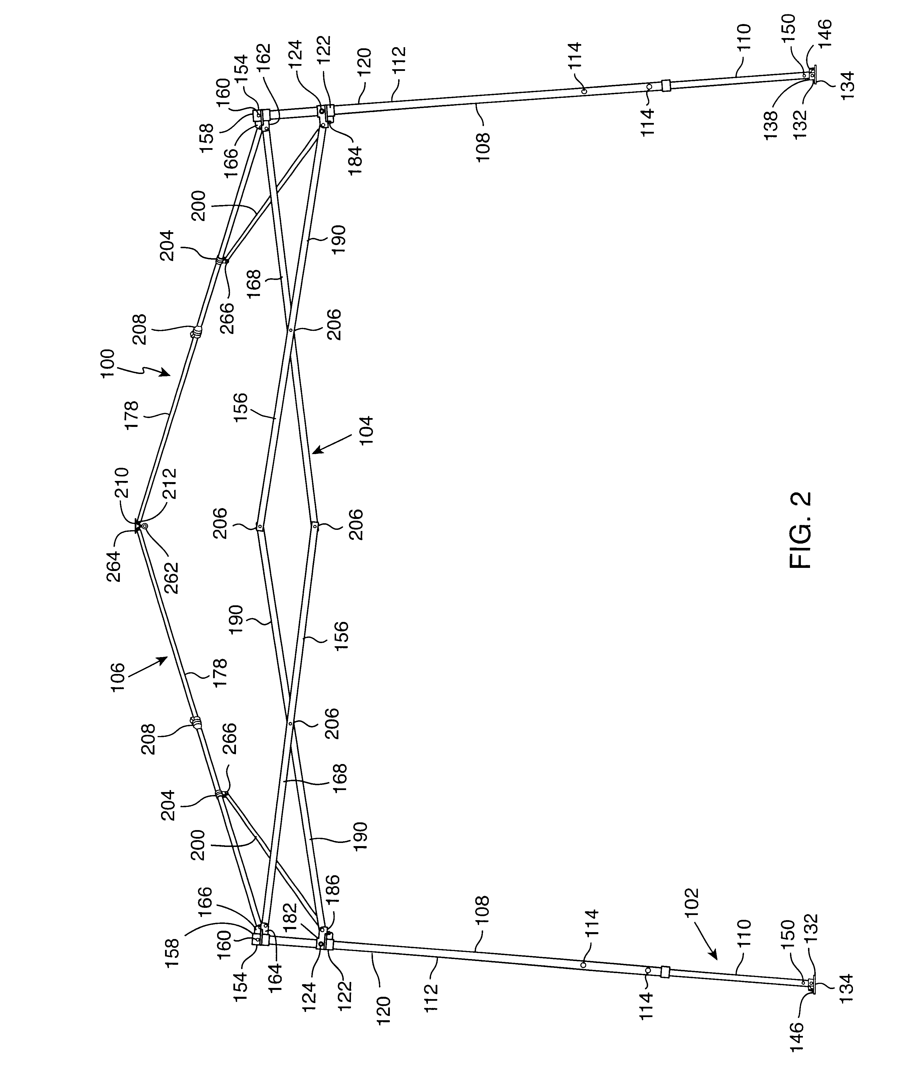
Briefly, and in general terms, the present invention provides a new and improved collapsible frame for use in erecting tents, insect screen rooms, shade awnings, canopies and the like in the out-of-doors such as campsites, back yard patios and other outdoor venues. The inventive collapsible frame exhibits a robust lightweight design including an aluminum frame. The collapsible frame is raised and lowered quickly and easily since each of the component elements remains connected in the collapsed position, i.e., the collapsible frame is a unitary structure. The height of the collapsible frame can be easily adjusted so that the superstructure provides adequate headroom for average height persons. When collapsed, the frame is transported and stored in a convenient carrying enclosure.
The collapsible frame of the present invention includes a plurality of four telescopic corner legs generally forming a rectangular pattern to create an upper support structure. Each telescopic corner leg includes an inner shaft and an outer shaft for adjusting the height thereof. A top corner joint is mounted to the top of each telescopic corner leg and a leg slider joint is positioned for translational motion along each of the corner legs. X-shaped truss pairs of link members (typically known in the art as a scissors connector) are positioned between each adjacent pair of telescopic corner legs for enabling the corner legs to be moved in a scissors fashion.
A superstructure comprised of four canopy support arms is fixedly attached to the upper support structure at the corresponding top corner joint and leg slider joint of each telescopic corner leg. The canopy support arms are connected together at the apex of the collapsible frame by a top joint connector. Each of the canopy support arms includes a spring loaded, locking pivotal connector which comprises a receiving cavity and a spring-loaded slide joined by a hinged junction. The spring-loaded slide includes a locking lip which is captured by the receiving cavity when the locking pivotal connector is in the locked position. A thumb knob is provided for operating the spring-loaded slide. Each of the telescopic corner legs also includes a base foot for improving the stability of the frame. Finally, a V-shaped, spring-loaded push button is employed for adjusting the height of each of the telescopic legs and for securing the position of the leg slider joint. This combination of components enables the collapsible frame to be raised and lowered as a unitary structure.

Problems solved by technology

Many of the collapsible frames of the prior art involve complicated articulated linkage which is difficult to manipulate.
This design results in a flimsy, unstable frame because it lacks unitary structure.
Also, many of the prior art frames are heavy and cumbersome to assemble and disassemble and thus are neither convenient nor desirable choices by persons of small physical stature.
Another common problem relates to the frequent misplacing or loss of some of the plurality of component parts necessary for the assembly of the frame.
As a result, certain components necessary to complete assembly of the frame may not be available and thus the effort to complete assembly of the frame is frustrated.
Although these frame apparatuses are collapsible and lightweight, many lack the structural integrity necessary to endure continuous usage and the elements.
Because the upper support structure of many of these frame apparatuses is not unitary with the lower support legs, these frames known in the prior art lack structural integrity and tend to be flimsy.

Method used


Image

  • Collapsible frame
  • Collapsible frame
  • Collapsible frame

Examples


Embodiment Construction

The present invention is a collapsible frame 100 as best shown in FIG. 1 for use in erecting tents, insect screen rooms, shade awnings, canopies and the like typically in the out-of-doors. The collapsible frame 100 of the present invention serves as a support by providing a structure for attaching material components such as canvas, netting, screens, plastic and the like for erecting tents, screen rooms, awnings and canopies as desired. The collapsible frame 100 is typically employed at campsites, roadside camping facilities for recreational vehicles, city parks, the seashore or even on the patio or in the back yard of a residence or other outdoor venue.

A preferred embodiment of the collapsible frame 100 is shown in FIGS. 1-24 and comprises three main categories which include a base portion 102, an upper support structure 104 and a superstructure 106. A description of the main components of each of these three main categories will now be set out in successive order.

The base portion ...


PUM


Abstract

A collapsible frame for use in erecting tents, canopies and the like at outdoor venues includes a plurality of telescopic legs for providing vertical structural support, and a plurality of top corner joints each fixedly mounted upon a top end of a corresponding telescopic leg. A leg slider joint is adjustably mounted upon each telescopic leg for sliding along that telescopic leg. A truss pair of link members is mounted to a pair of top corner joints and to a corresponding pair of leg slider joints. The link members are mounted on adjacent pairs of telescopic legs for providing a scissors connector. Finally, a plurality of canopy support arms, each including a locking pivotal connector and each fixedly connected to a top corner joint and a corresponding leg slider joint, is employed for raising and lowering the collapsible frame as a stable unitary structure.

Description

BACKGROUND OF THE INVENTION1. Technical FieldThe present invention relates to the assembly and disassembly of temporary structures and other protective shelters typically in the out-of-doors. More specifically, the present invention relates to methods and apparatus for a collapsible frame of unitary structure for use in erecting tents, insect screen rooms, shade awnings, canopies and the like at campsites, back yard patios and other outdoor venues.2. Background ArtThe relevant art is directed to collapsible frames utilized in erecting temporary structures for use in the out-of-doors. The typical frame apparatus of the prior art is employed in combination with, for example, a canopy as a temporary shelter, or as a frame for a tent to serve various functions in the outdoors.The outdoor venue in which the frame apparatus of the prior art is typically utilized varies widely. The outdoor venue can be a campsite for hunting, fishing, hiking, rock climbing, a roadside camping facility for ...

Claims


Application Information

Patent Timeline
IPC IPC(8): E04H15/34E04H15/50
CPCE04H15/50
Inventor PRICE, ROY JUSTIN
Owner PRICE ROY JUSTIN
Learn More