
Signal transmission cable structure

a signal transmission cable and structure technology, applied in the direction of cables, power cables, cable arrangements between relatively moving parts, etc., can solve the problems of additional connecting, inconvenient receiving of conventional signal transmission cables in device bodies, and cylindrical outer shapes, so as to reduce the occupation space, prevent interference, and facilitate winding

Inactive Publication Date: 2004-07-20
HSIEH ANGUS
View PDF3 Cites 17 Cited by
  • Summary
  • Abstract
  • Description
  • Claims
  • Application Information

AI Technical Summary

Benefits of technology

"The invention is a signal transmission cable that is flat and flexible, making it easy to wound in a cable-receiving case and prevent interference between different lines within the cable. The cable does not require a nylon thread to have good flexibility, reducing manufacturing costs. The cable includes an insulating body, a woven fabric layer, a tin foil layer, two signal lines, two power lines, and an insulating layer made of foam polyethyl. The cable is formed in a flat and flexible shape with a width of about 4.5 to 8 mm. The technical effects of the invention are that it prevents interference between different lines within the cable, reduces the occupation space when received within a device body, and is aesthetically pleasing."

Problems solved by technology

Although the above conventional signal transmission cable has good signal transmission results, its outer shape however is cylindrical and occupies a substantial space when being wound.
The conventional signal transmission cable cannot be therefore conveniently received in a device body and need an external receiving member.
If the user carries outdoor the electronic device to which the conventional signal transmission cable is connected, the user further needs to take with him / her several additional connecting lines which connection is time-consuming.
The additional connecting lines further take substantial occupation space and may be lost.
If the signal transmission cable is outwardly laid on a flat surface, the resulting protrusion of the cable is not aesthetic and further may easily causes a walking person to stumble.
Moreover, with a cylindrical outer shape, the different lines within the cable are separated with a relatively small spacing distance, which easily causes interference.
Because bending of the cylindrical cable may further negatively affects the signal transmission, the nylon thread is therefore traditionally needed to increase the flexibility of the cable, which increases the fabrication cost.

Method used


Image

  • Signal transmission cable structure
  • Signal transmission cable structure
  • Signal transmission cable structure

Examples


Embodiment Construction

Wherever possible in the following description, like reference numerals will refer to like elements and parts unless otherwise illustrated.

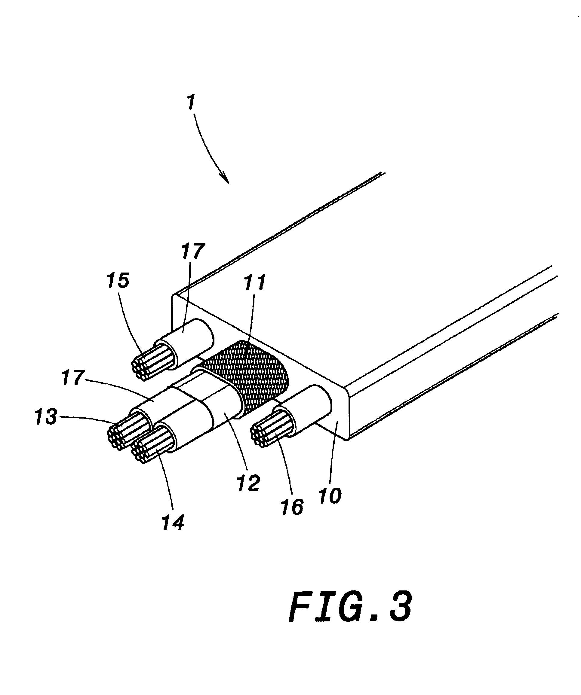
Referring to FIG. 3 and FIG. 4, a perspective view and a cross-sectional view schematically illustrate a structure of signal transmission cable according to a first embodiment of the invention. As shown, a signal transmission cable comprises an insulating body 10, a woven fabric layer 11, a tin foil 12, two signal lines 13, 14 and two power lines 15, 16. The insulating body 10 is the outmost layer of the cable 1, and is made of polyvinylchloride having good thermosetting properties. Within the insulating body 10 is arranged the woven fabric layer 11 acting as anti-interference protection. Within the woven fabric layer 11 is arranged the tin foil 12 that encapsulates the two signal lines 13, 14. Around the periphery of signal lines 13, 14 is respectively arranged an insulating layer 17 made of foam polyethyl having good thermosetting properties. A...


PUM

PropertyMeasurementUnit
spacing distanceaaaaaaaaaa
widthaaaaaaaaaa
flexibleaaaaaaaaaa

Abstract

A signal transmission cable, formed in a flat and flexible shape, comprises an insulating body as outmost layer of the signal transmission cable. A woven fabric layer is arranged within the insulating body. A tin foil is arranged within the woven fabric layer. Two signal lines are encapsulated within the tin foil, and two power lines are placed within the insulating body. The signal lines and the power lines respectively are covered with an insulating layer. The signal transmission cable therefore constructed is easily wound and reduces the fabrication cost.

Description

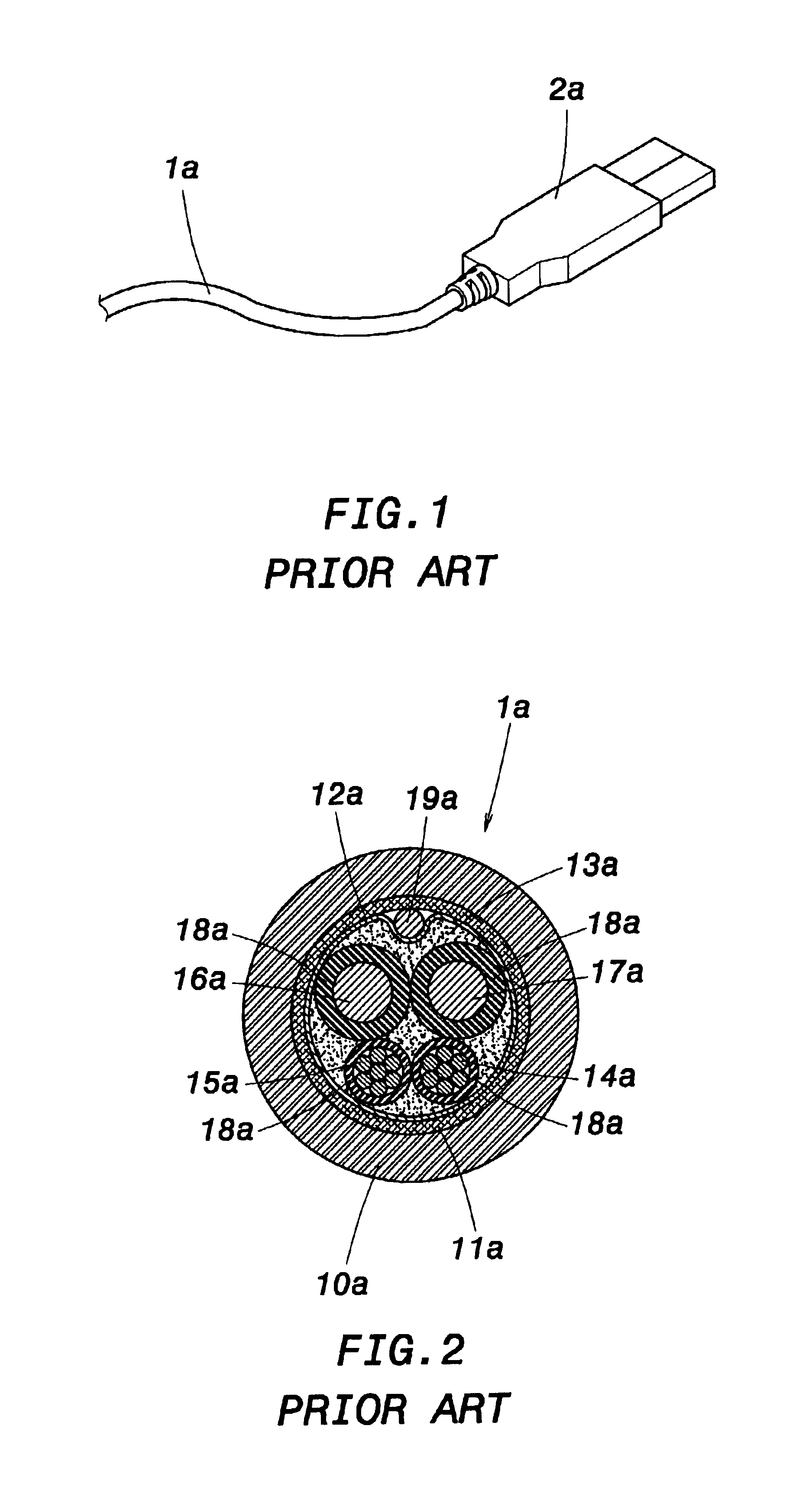
1. Field of the InventionThe invention relates to a signal transmission cable structure and, more particularly, to a signal transmission cable formed in flat and flexible shape.2. Description of the Related ArtA signal transmission cable is conventionally used to connect, for example, a telephone handset or different computer components.FIG. 1 and FIG. 2 are respectively a perspective view and a cross-sectional view showing a conventional signal transmission cable. As shown, a conventional signal transmission cable 1a is usually cylindrical, and comprises an insulating body 10a, a woven fabric layer 11a, a tin foil 12a, a nylon thread 13a, a ground line 19a, an insulating layer 18a, two signal lines 14a, 15a and two power lines 16a, 17a. The insulating body 10a is made of PVC having good insulating properties, and is the outmost layer of the signal transmission cable 1a. The woven fabric layer 11a is placed within the insulating body 10a, and acts as anti-interference protection. Th...

Claims


Application Information

Patent Timeline
Patent Type & Authority Patents(United States)
IPC IPC(8): H01B9/00H01B7/08H02G11/02H02G11/00
CPCH01B7/0861H01B9/003H02G11/02
Inventor HSIEH, ANGUS
Owner HSIEH ANGUS
Learn More