
Failure determination system and method for internal combustion engine and engine control unit

a technology of failure determination system and engine control unit, which is applied in the direction of electric control, machines/engines, instruments, etc., can solve the problems of inability to determine whether the misfire occurs, the conventional control system suffers, and the cylinders are unable to fir

Inactive Publication Date: 2004-07-20
HONDA MOTOR CO LTD
View PDF8 Cites 70 Cited by
  • Summary
  • Abstract
  • Description
  • Claims
  • Application Information

AI Technical Summary

Benefits of technology

The invention is a failure determination system for an internal combustion engine and its engine control unit. The system is designed to detect and determine the cause of misfires in the engine. The system uses a variable valve mechanism to inactivate valves in certain cylinders during certain operating conditions of the engine. The system detects misfires on a cylinder-by-cylinder basis and stops fuel injection to the affected cylinders. The system can determine if the failure is due to a failure of the variable valve mechanism or unstable combustion in the misfiring cylinder. This allows for proper copping with the cause of the misfire and ensures proper engine performance.

Problems solved by technology

However, the conventional control system suffers from the following problems: Internal combustion engines include a type which has a variable valve mechanism for inactivating predetermined ones of cylinders during deceleration of the vehicle.
As a result, in the case of this kind of engine, if a failure of the variable valve mechanism has occurred, the intake and exhaust valves, which should open and close for operation of the cylinders as their inherent function, are sometimes held closed, causing misfires in these cylinders.
However, in the conventional control system, since detection of a misfire is carried out only based on variation in the rotational speed of the crankshaft, it is impossible to determine whether the misfire occurs due to a failure of the variable valve mechanism or due to unstable combustion in the misfiring cylinder (normal misfire).
This makes it impossible to properly cope with a misfire in a manner suited to the cause of the misfire.

Method used


Image

  • Failure determination system and method for internal combustion engine and engine control unit
  • Failure determination system and method for internal combustion engine and engine control unit
  • Failure determination system and method for internal combustion engine and engine control unit

Examples


Embodiment Construction

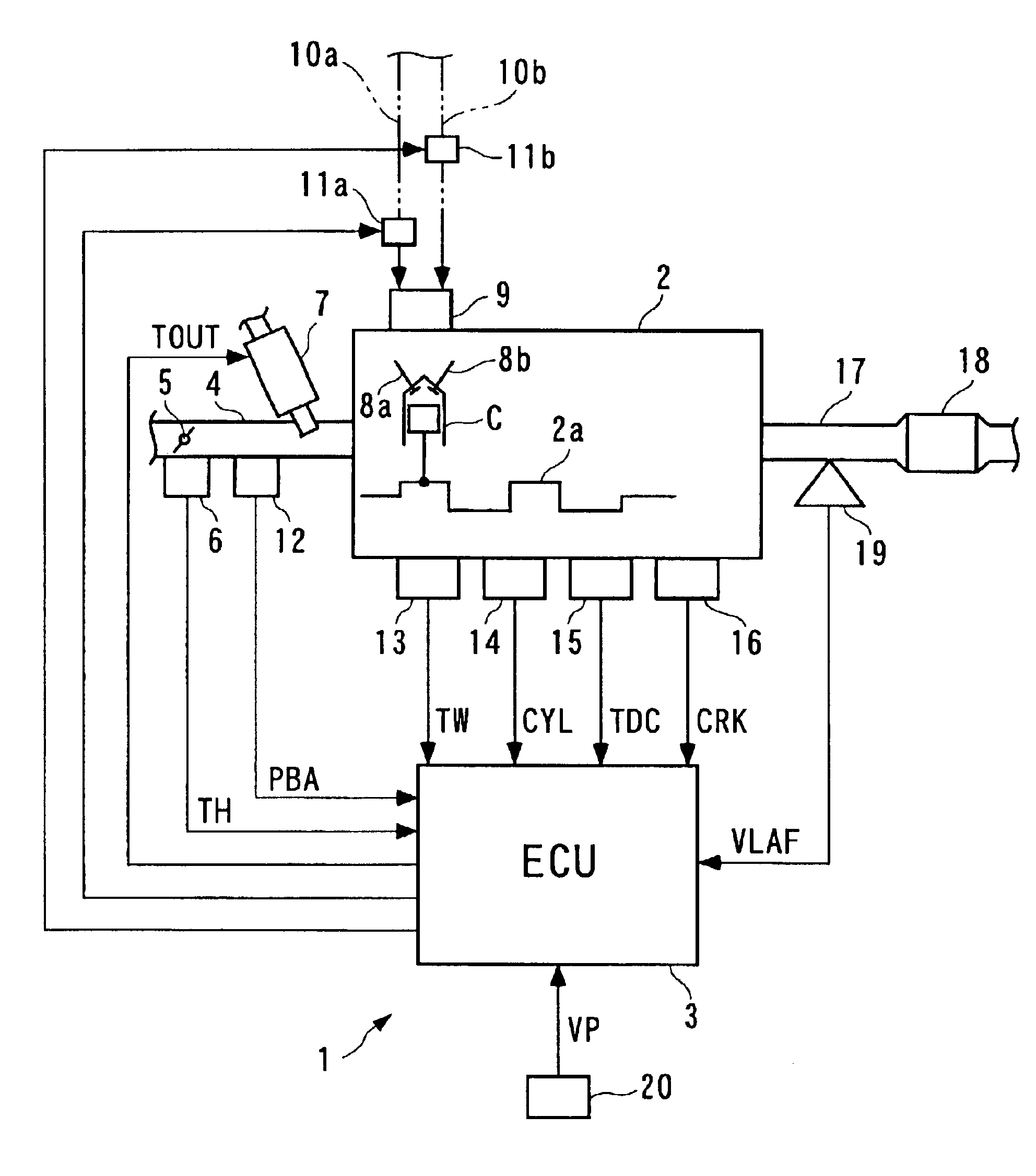
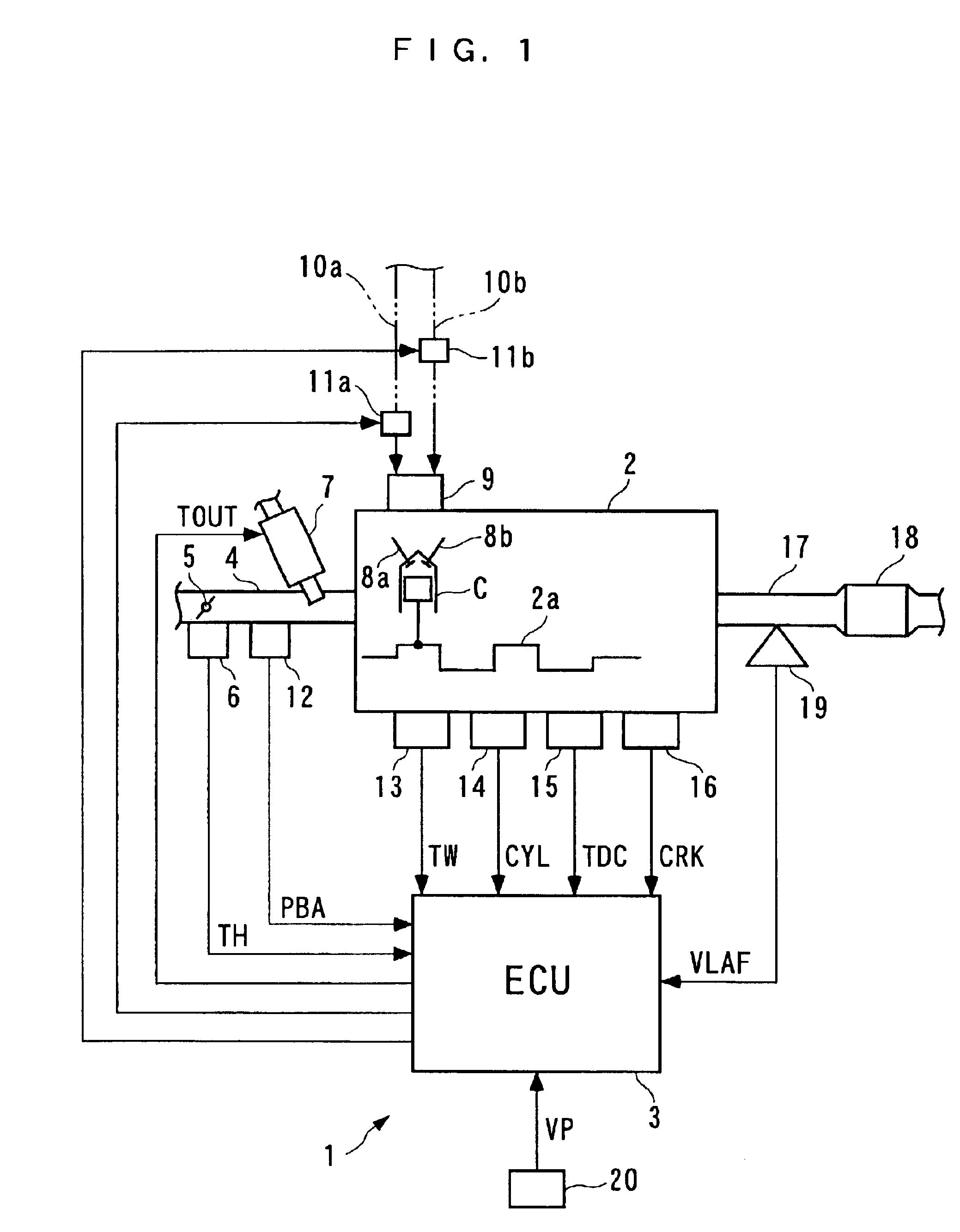
The invention will now be described in detail with reference to the drawings showing a preferred embodiment thereof. Referring first to FIG. 1, there is schematically shown the arrangement of an internal combustion engine 2 to which is applied a failure determination system 1 according to an embodiment of the invention.

The internal combustion engine (hereinafter simply referred to as "the engine") 2 is a four-cylinder DOHC gasoline engine including e.g. #1 to #4 cylinders C (only one of which is shown in FIG. 1), installed on a vehicle, not shown. The engine 2 has an intake pipe 4 having a throttle valve 5 arranged therein. A degree of opening of the throttle valve 5 (hereinafter referred to as "the throttle valve opening") TH is sensed by a throttle valve opening sensor 6, and a signal indicative of the sensed throttle valve opening TH is supplied to an ECU 3, referred to hereinafter. The intake pipe 4 has fuel injection valves (hereinafter referred to as "injectors", only one of w...


PUM

PropertyMeasurementUnit
timeaaaaaaaaaa
timeaaaaaaaaaa
timeaaaaaaaaaa

Abstract

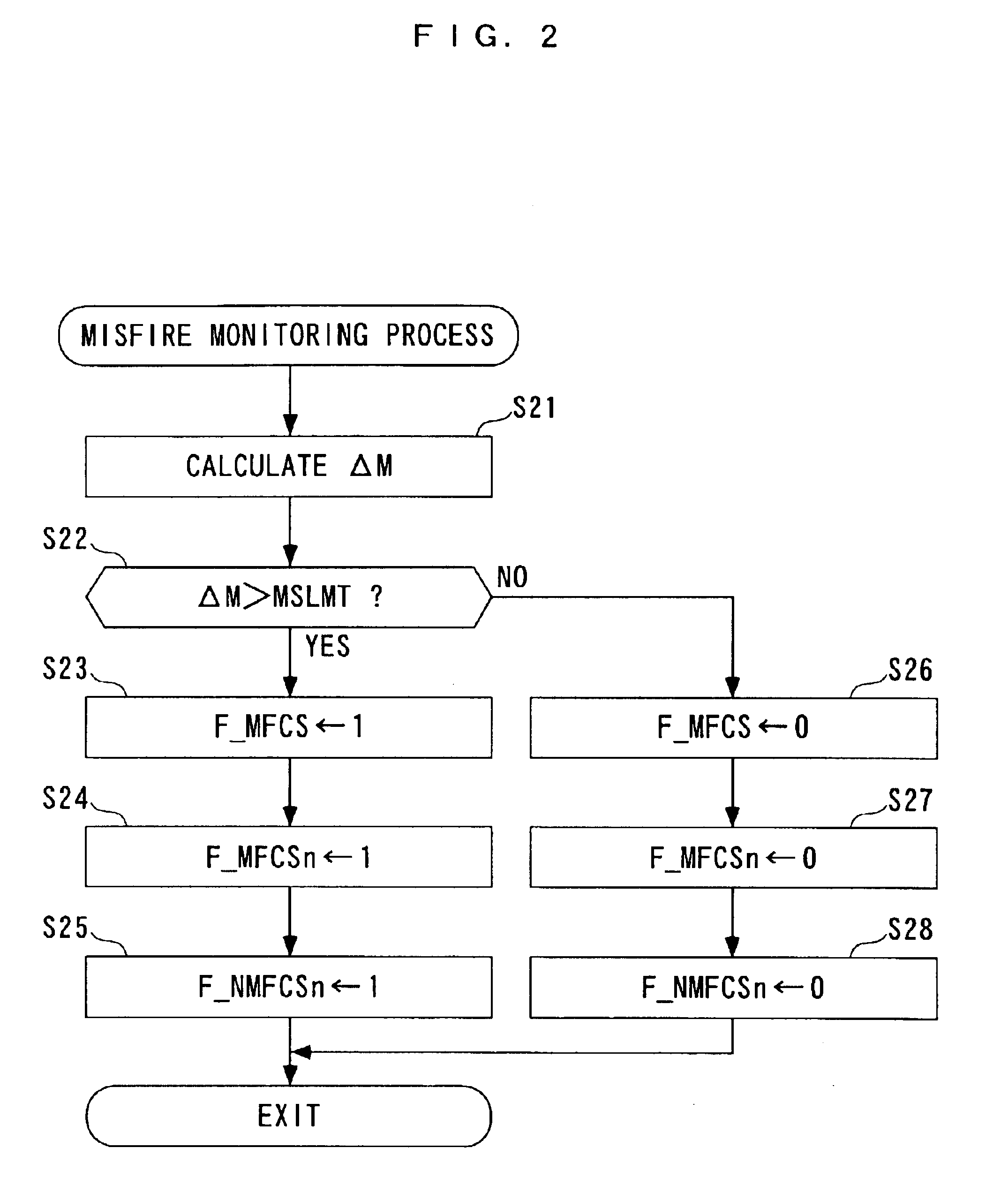
A failure determination system and method for an internal combustion engine and an engine control unit are provided which are capable of properly determining a failure of a variable valve mechanism for inactivating a valve system associated with at least one of cylinders during a predetermined operation of the engine, by discriminating a misfire caused by the failure of the mechanism from a normal misfire. Fuel injection valves inject fuel for each cylinder and oxygen concentration of exhaust gases is detected. A misfire condition is detected on a cylinder-by-cylinder basis. Fuel injection to a misfiring cylinder is stopped. A failure of the mechanism is determined, when a parameter based on the oxygen concentration detection indicates a richer value of an actual air-fuel ratio of the exhaust gases than a predetermined reference value does, under a condition of the fuel injection being stopped.

Description

1. Field of the InventionThis invention relates to a failure determination system and method for an internal combustion engine and an engine control unit, and more particularly to a failure determination system and method and an engine control unit, for determining a failure of a variable valve mechanism which inactivates a valve system associated with at least one of cylinders during a predetermined operation of the engine.2. Description of the Prior ArtConventionally, a control system for an internal combustion engine has been disclosed e.g. in the publication of Japanese Patent No. 2507550. The control system is used for controlling the fuel supply and cut-off of the fuel supply depending on a misfire condition of the engine. More specifically, the control system detects a misfire condition, on a cylinder-by-cylinder basis, based on variation in the rotational speed of a crankshaft, and cuts off the supply of fuel to a cylinder in which a misfire has been determined to occur, for...

Claims


Application Information

Patent Timeline
Patent Type & Authority Patents(United States)
IPC IPC(8): F02D41/22F02D41/12G01M15/04G01M15/10F02D13/02F02D13/06F02D41/00F01L1/46F02D45/00
CPCF02D13/06F02D41/0087F02D41/221G01M15/104F02D41/12F02D41/1454F02D41/1456F02D2041/001F02D2041/0012F02D2200/0404F02D2200/0406Y02T10/40Y02T10/18Y02T10/12
Inventor KUMAGAI, KATSUHIROKITAJIMA, SHINICHINISHIOKA, FUTOSHISHINOHARA, TOSHINARINAKAUNE, KANMATSUBARA, ATSUSHI
Owner HONDA MOTOR CO LTD
Learn More