
Microfluidic devices and systems incorporating cover layers

a microfluidic device and cover layer technology, applied in the field of microfluidic devices and systems incorporating cover layers, can solve the problems of reducing the required volume of potentially very expensive test compounds, and the difficulty of miniaturization in the use of such systems, so as to improve material handling characteristics and reduce manufacturing costs

Inactive Publication Date: 2004-06-29
CAPLIPER LIFE SCI INC
View PDF80 Cites 267 Cited by
  • Summary
  • Abstract
  • Description
  • Claims
  • Application Information

AI Technical Summary

Benefits of technology

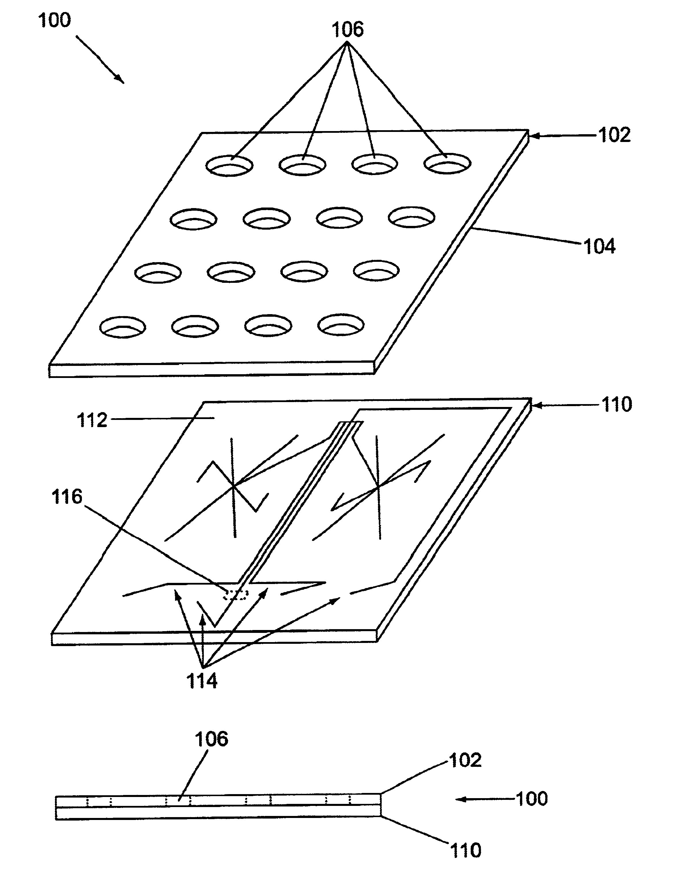
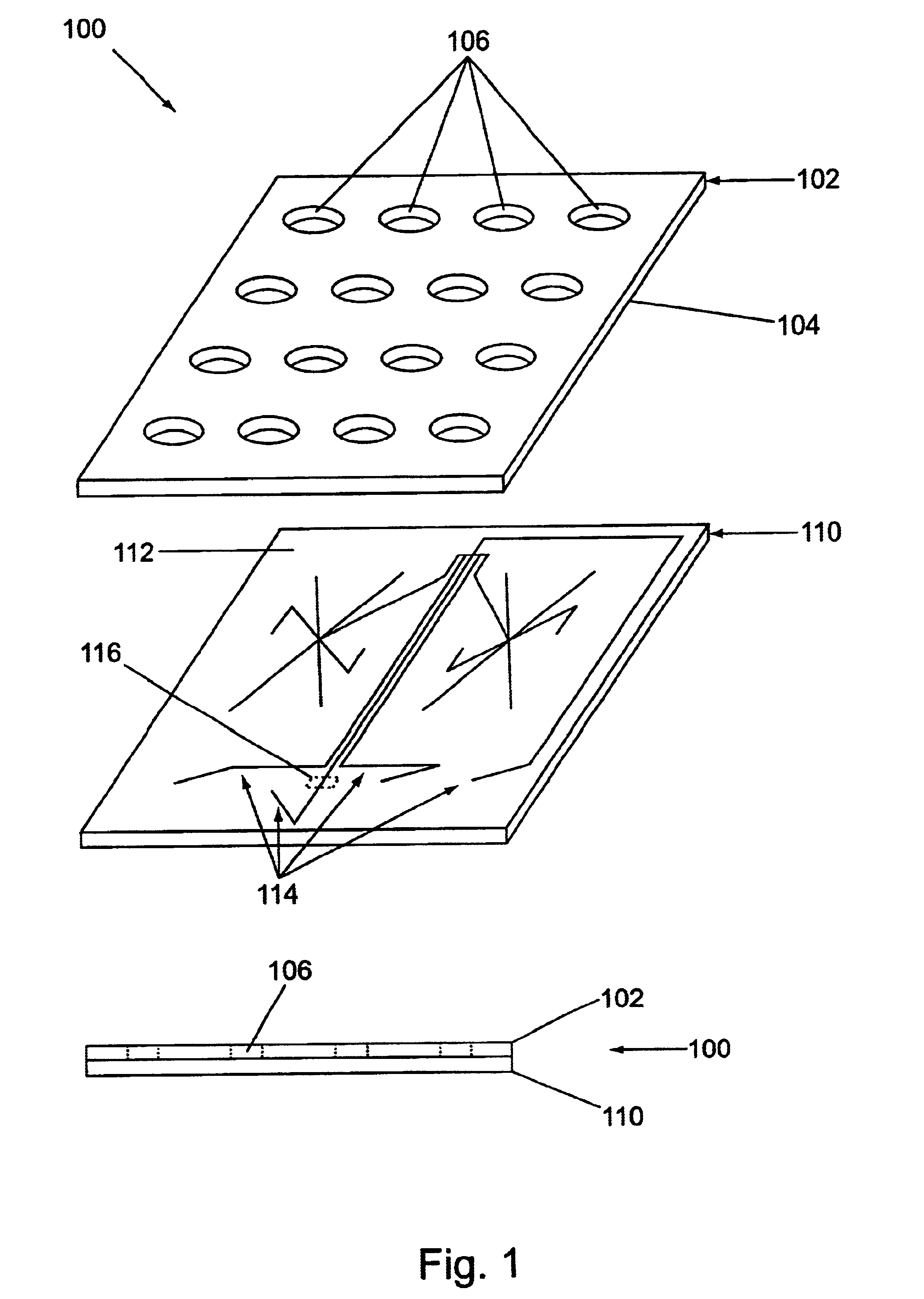
It is a general object of the present invention to provide microfluidic devices and methods that combine the advantages of microfluidics with improved material handling characteristics and reduced costs for manufacturing. The present invention accomplishes this in a first aspect, by providing microfluidic devices that incorporate a body structure comprising at least a first microscale channel network disposed therein. The body structure has a plurality of ports disposed in it, where each port is in fluid communication with one or more channels in the first channel network. The devices also include a cover layer comprising a plurality of apertures disposed therethrough. The cover layer is mated with the body structure whereby each of the apertures is aligned with a separate one of the plurality of ports.
In another embodiment, the microfluidic devices of the present invention also optionally include a membrane (e.g., a semi-permeable membrane or the like) disposed between at least one pair of aligned apertures and ports, which together form wells, for sieving aggregations of material (e.g., aggregations of cells, molecules, etc.) and / or delivering various reagents to the devices. The membrane is also optionally disposed on or over the wells. The invention additionally includes embodiments in which at least a portion of the wells of the devices include a conductive coating. The use of conductive coatings, inter alia, minimizes cross-contamination between microfluidic devices. Furthermore, the invention also includes other embodiments in which rings, membranes, and / or conductive coatings are used in various combinations in the devices.

Problems solved by technology

Again, these systems reduce the required volumes of potentially very expensive test compounds, e.g., drug candidates, library compounds, etc.
Despite the numerous advantages realized by the miniaturization of analytical systems, such miniaturization can provide difficulties in the use of such system including user handling, reagent delivery or filtration, and system interfacing of such devices.

Method used


Image

  • Microfluidic devices and systems incorporating cover layers
  • Microfluidic devices and systems incorporating cover layers
  • Microfluidic devices and systems incorporating cover layers

Examples


Embodiment Construction

I. General

The present invention generally provides microfluidic devices and methods that take advantage of the extremely small-scale nature of microfluidic devices and systems, while at the same time, not suffering from some of the potential problems associated with such systems. In particular, the microfluidic devices and systems of the invention include an additional cover layer as a portion of the microfluidic device, e.g., overlaying and attached to the basic body structure of the device. The cover layer employed in the devices of the invention typically comprises a number of apertures disposed through it, which apertures mate with and / or form part of the reservoirs and / or access ports of the microfluidic device. These cover layers provide a number of advantages in the operation and fabrication of microfluidic devices.

As used herein, the terms "microscale," "microfabricated" or "microfluidic" generally refer to one or more fluid passages, chambers or conduits which have at least...


PUM


Abstract

The present invention provides microfluidic devices that comprise a body structure comprising at least a first microscale channel network disposed therein. The body structure has a plurality of ports disposed in the body structure, where each port is in fluid communication with one or more channels in the first channel network. The devices also include a cover layer comprising a plurality of apertures disposed through the cover layer. The cover layer is mated with the body structure whereby each of the apertures is aligned with a separate one of the plurality of ports. Rings are optionally disposed between the cover layer and the body structure and circumferentially around pairs of aligned apertures and ports. The devices also optionally include conductive coatings and membranes. The invention additionally provides methods of controlling the delivery of a composition of material into a microfluidic device.

Description

BACKGROUND OF THE INVENTIONAs has been the case in the electronics and computer industries, trends in analytical chemical and biochemical instrumentation have been toward miniaturization. In chemical and biochemical analyses, such miniaturization as achieved in e.g., microfluidic systems, provides numerous advantages, including significantly smaller reagent requirements, faster throughput, ready automatability, and in many cases, improved data.By way of example, U.S. Pat. Nos. 5,498,392 and 5,587,128 describe the performance of amplification reactions in microfabricated devices including microscale flow systems and / or reaction chambers. Such systems substantially reduce the requirements for expensive reagents utilized in amplification reactions. Further, the small scale of these devices also provides for enhanced thermal transfer between heating sources and the reagents in the device.Similarly, U.S. Pat. No. 5,637,469 describes the use of devices having extremely small internal dime...

Claims


Application Information

Patent Timeline
IPC IPC(8): B01L3/00G01N27/447G01N35/00
CPCB01L3/502715G01N27/44791B01L3/5085Y10T436/25B01L2200/025B01L2200/027B01L2200/0605B01L2200/0689B01L2300/0681B01L2300/0887B01L2300/16B01L2400/0406B01L2400/0415B01L2400/0487G01N2035/00148Y10T436/25625Y10T436/2575
Inventor DUBROW, ROBERT S.KENNEDY, COLIN B.NAGLE, ROBERTCHAZAN, DAVIDLEE, ERNEST C. W.GANDHI, KHUSHROOCHOW, CALVIN Y. H.
Owner CAPLIPER LIFE SCI INC
Learn More