
Routing structures for a tileable field-programmable gate array architecture

a gate array and tileable technology, applied in the direction of computation using denominational number representation, pulse technique, instruments, etc., can solve the problems of not being flexible and unable to be reconfigured to perform a different function

Inactive Publication Date: 2004-05-04
MICROSEMI SOC
View PDF32 Cites 133 Cited by
  • Summary
  • Abstract
  • Description
  • Claims
  • Application Information

AI Technical Summary

Benefits of technology

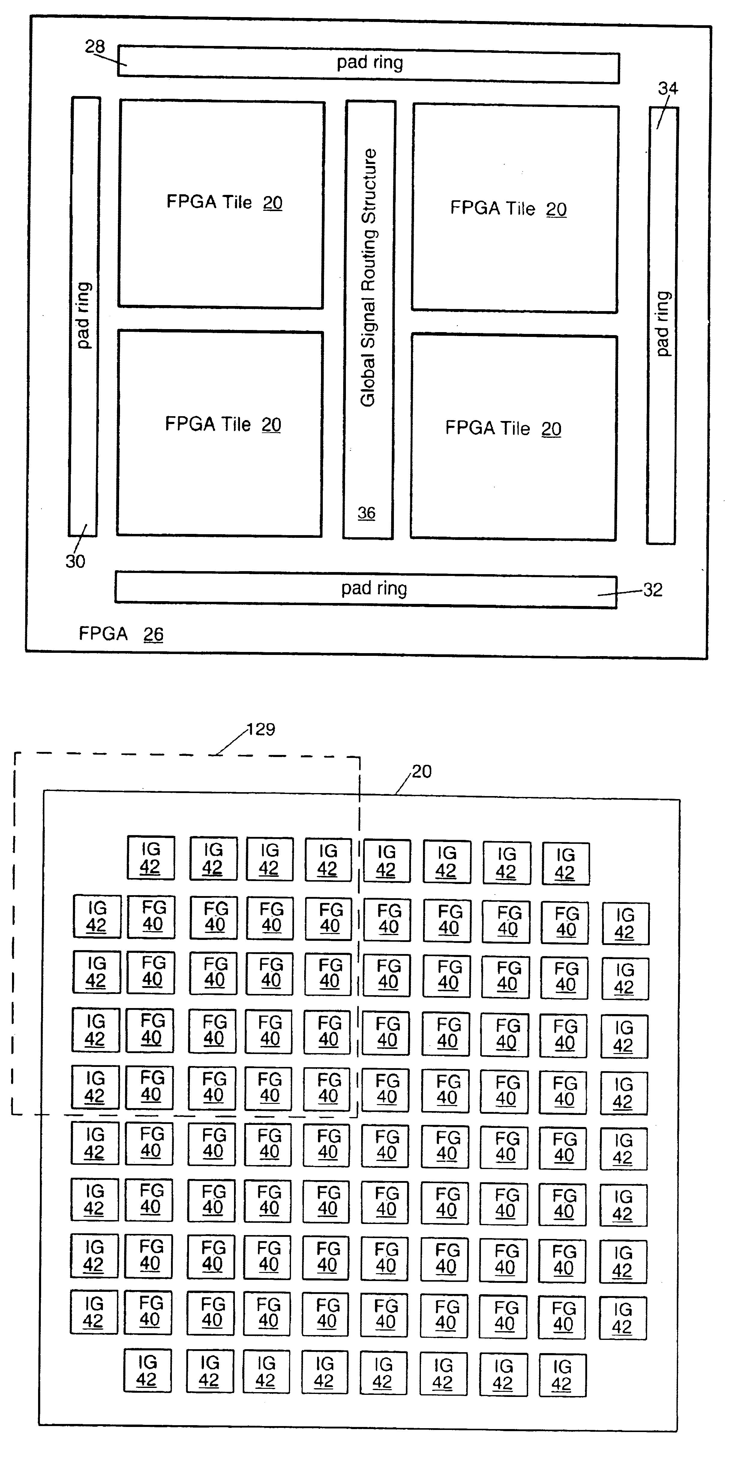
The present patent describes a system that includes a field-programmable gate array (FPGA) with a first FPGA tile that has a plurality of functional groups (FGs), a regular routing structure, and a plurality of interface groups (IGs). The FGs are arranged in rows and columns with each FG being configured to receive regular input signals, perform a logic operation, and generate regular output signals. The regular routing structure is coupled to the FGs and is configured to receive the regular output signals, route signals within the first FPGA tile, and provide the regular input signals to the FGs. The first FPGA tile also has a secondary routing structure that is independent of the regular routing structure and is coupled to each of the IGs. The system also includes a routing structure between the IGs and RAM blocks. The technical effects of the present patent include improved programmability, flexibility, and efficiency of the FPGA system.

Problems solved by technology

An ASIC, on the other hand, is not a flexible device.
In other words, once an ASIC has been designed and manufactured it cannot be reconfigured to perform a different function like is possible with an FPGA.

Method used


Image

  • Routing structures for a tileable field-programmable gate array architecture
  • Routing structures for a tileable field-programmable gate array architecture
  • Routing structures for a tileable field-programmable gate array architecture

Examples


Embodiment Construction

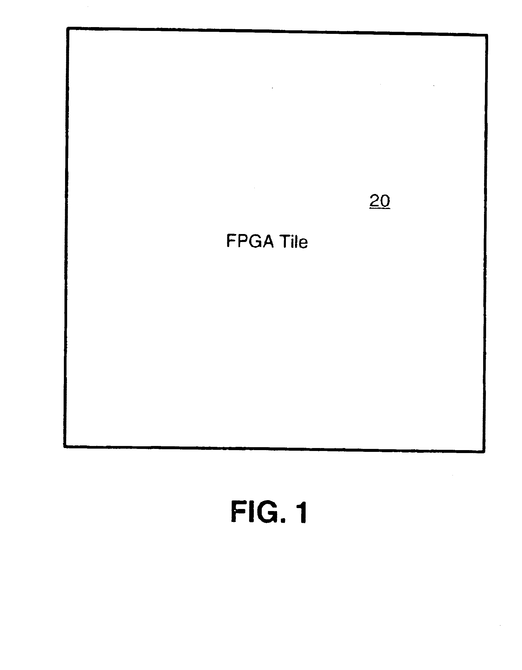
Referring to FIG. 1, there is illustrated a field-programmable gate array (FPGA) tile 20 in accordance with the present disclosed system. The FPGA tile 20 overcomes many of the disadvantages of conventional FPGAs in that it can be easily adapted for use in both integrated circuits (ICs) requiring large FPGAs and ICs requiring small FPGAs. Furthermore, the FPGA tile 20 can be used where the FPGA is to be manufactured as its own IC and where the FPGA is to be embedded into a larger IC (e.g., a system on a chip (SOC)).

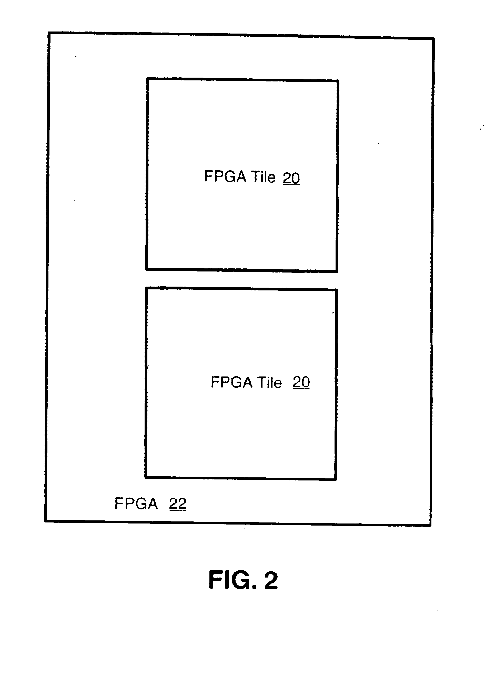
One feature of the FPGA tile 20 that makes it such a flexible and adaptable device is that it is "tileable". As used herein, the term "tileable" means that the FPGA tile 20 can be combined with other FPGA tiles to form a larger FPGA. For example, FIG. 2 illustrates an FPGA 22 that is formed by combining two FPGA tiles 20. The two FPGA tiles 20 work together and communicate with each other to form the larger FPGA 22. It should be well understood that any number of FPGA til...


PUM


Abstract

A field-programmable gate array (FPGA), comprising: a first FPGA tile, the first FPGA tile comprising a plurality of functional groups (FGs), a regular routing structure, and a plurality of interface groups (IGs). The plurality of FGs are arranged in rows and columns with each of the FGs being configured to receive regular input signals, perform a logic operation, and generate regular output signals. The regular routing structure is coupled to the FGs and configured to receive the regular output signals, route signals within the first FPGA tile, and provide the regular input signals to the FGs. The plurality of IGs surround the plurality of FGs such that one IG is positioned at each end of each row and column. Each of the IGs is coupled to the regular routing structure and configured to transfer signals from the regular routing structure to outside of the first FPGA tile. The first FPGA tile also comprising a secondary routing structure independent of the regular routing structure, coupled to each of the IGs, configured to transfer signals from said first FPGA tile to at least one other FPGA tile. The disclosed apparatus also provides for a routing structure between IGs and RAM blocks. It is emphasized that this abstract is provided to comply with the rules requiring an abstract that will allow a searcher or other reader to quickly ascertain the subject matter of the technical disclosure. It is submitted with the understand that it will not be used to interpret or limit the scope or meaning of the claims.

Description

BACKGROUND OF THE DISCLOSED SYSTEM1. Field of the Disclosed SystemThe present disclosed system relates to field-programmable gate arrays, and more particularly, to an architecture for tileable field-programmable gate arrays.2. Description of the Related ArtA field-programmable gate array (FPGA) is an integrated circuit (IC) that includes a two-dimensional array of general-purpose logic circuits, called cells or logic blocks, whose functions are programmable. The cells are linked to one another by programmable buses. The cell types may be small multifunction circuits (or configurable functional blocks or groups) capable of realizing all Boolean functions of a few variables. The cell types are not restricted to gates. For example, configurable functional groups typically include memory cells and connection transistors that may be used to configure logic functions such as addition, subtraction, etc., inside of the FPGA. A cell may also contain one or two flip-flops. Two types of logic ...

Claims


Application Information

Patent Timeline
Patent Type & Authority Patents(United States)
IPC IPC(8): H03K19/177
CPCG06F17/5054G06F17/5077H03K19/17732H03K19/17736H03K19/17796G06F30/34G06F30/394G06F30/3947G06F30/347
Inventor FENG, SHENGLIEN, JUNG-CHEUNHUANG, EDDY C.SUN, CHUNG-YUANLIU, TONGLIAO, NAIHUI
Owner MICROSEMI SOC
Learn More