
Machine for profile working of front surfaces on oblong wood workpieces

a technology for working surfaces and workpieces, applied in the manufacture of veneers, wood sticks, chemical debarking, etc., can solve the problems of inability to make any accurate, inability to accurately work on the front surface of the profile, and inability to meet the requirements of production

Inactive Publication Date: 2004-04-27
LEDINEK PAVEL +1
View PDF12 Cites 17 Cited by
  • Summary
  • Abstract
  • Description
  • Claims
  • Application Information

AI Technical Summary

Benefits of technology

"The invention is a machine for profile working of front surfaces on oblong wood workpieces. It includes a transverse set up entrance roller conveyor, longitudinal conveyor, entrance turnover device, oblique roller conveyor, longitudinal conveyor, endless conveying chain with clamping units and oblique roller conveyor, circular saw, profile miller, glue depositor, oblique conveyor, longitudinal conveyor, circular saw, profile miller, glue depositor, exit turnover device, longitudinal conveyor, transverse roller conveyor, and straightening rolls. The machine is designed to allow for continuous working of front surfaces on oblong wood workpieces, with intermediate stops for adjusting the position of the workpiece before and after the working process."

Problems solved by technology

It is further also evident that they do not make any accurate positioning or a larger number of workpieces inside the clamping device before and during clamping front surface adjustment feasible, what inevitably causes inaccuracy of profile front surface working, and therewith intolerable discrepancy or aeration inside the built up toothed joint, what entails in not quality finished toothed joints on front surfaces, and the product built up of glued workpieces greater or smaller curvature.
Both solutions are also impractical, as they are exclusively applicable for profile working of smaller intersections wood workpieces front surfaces, and do not make such working of workpieces larger intersections feasible.
This known solution weakness and deficiency are above all in the complex and very demanding construction, the capacity of which is limited due to the circular working mode, as well as in the workpieces unreliable transverse shift among working units.
This known solution weakness and deficiency are in the machine capacity limit depending on intermediate operations, the machine does not make the front surface profile working of different lengths and smaller intersections workpieces feasible, and further the working is also lagged behind provided the workpieces are twisted along the longitudinal and / or transversal axis, or otherwise deformed.
This known solution weakness and deficiency are in the fact that it is exclusively applicable for very flat workpieces of a very low quader form with a large area basic surface, and for low speeds, which all strongly decrease the machine capacity.
All the aforesaid known solutions common characteristics that simultaneously represent an outstanding problem in the profile both sides front surface working of optional lengths and intersections oblong workpieces are above all in working limitation of various intersections and lengths workpieces, in the working stroke procedure, unreliable clamping of workpieces during working, and likewise their conveying and turnover, possibility of frequent stoppages during working owing to deformed workpieces and machine damages in connection with it, as well as a relatively low capacity of these machines.

Method used


Image

  • Machine for profile working of front surfaces on oblong wood workpieces
  • Machine for profile working of front surfaces on oblong wood workpieces
  • Machine for profile working of front surfaces on oblong wood workpieces

Examples


Embodiment Construction

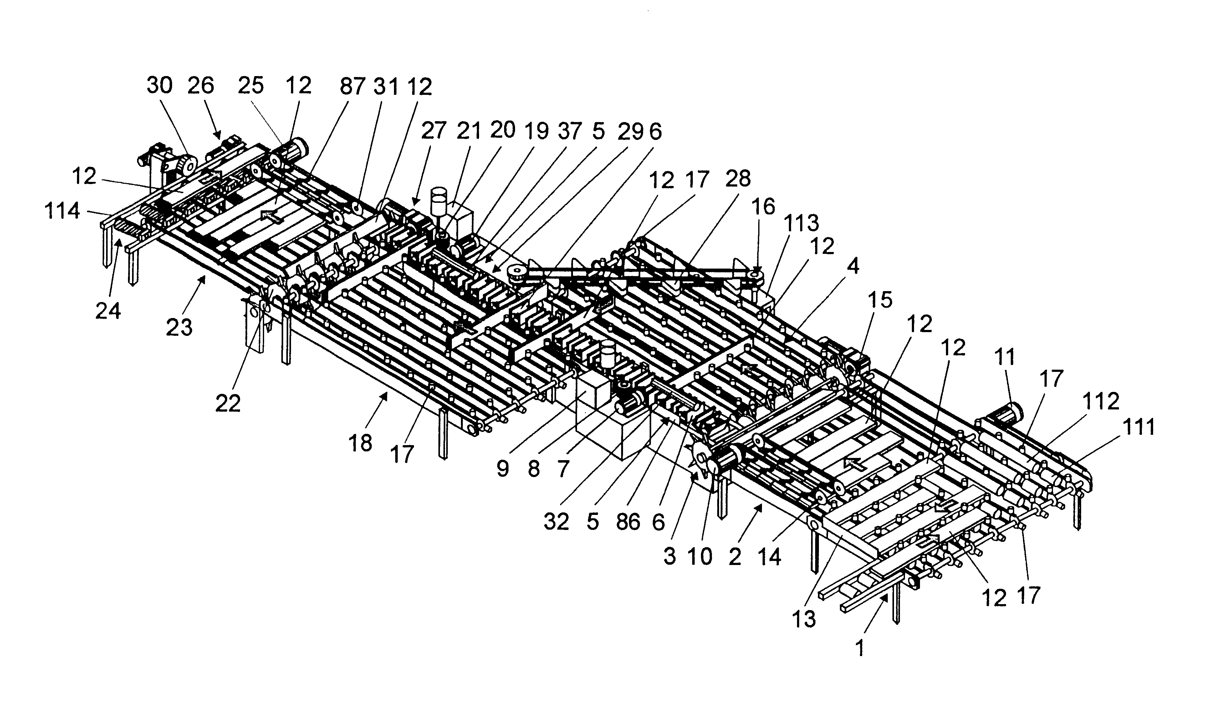
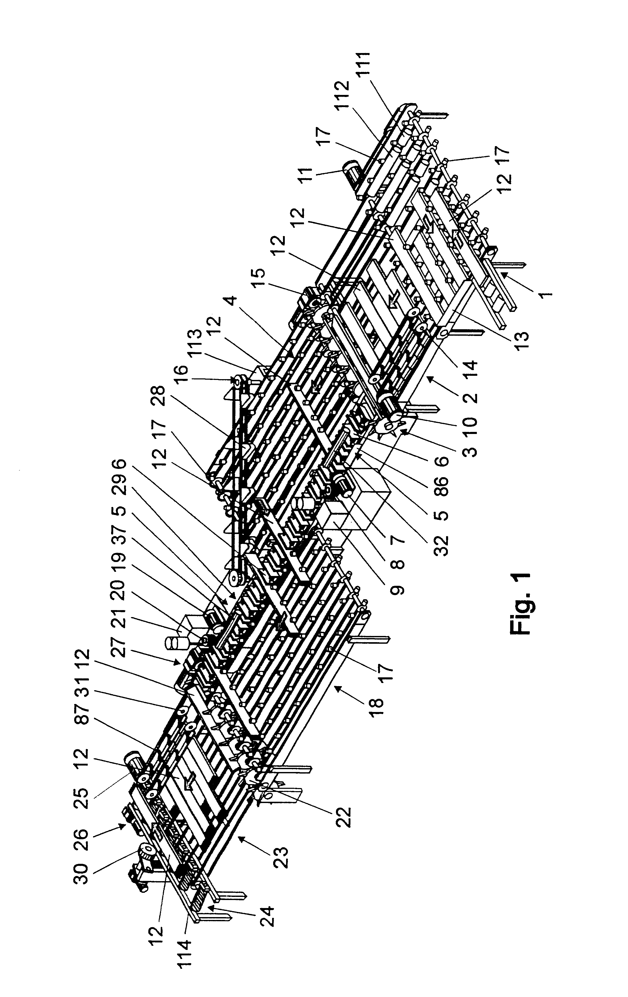
Turning now to the drawings, and referring first to the FIG. 1, the machine for profile working of front surfaces on oblong wood workpieces is constructed of the transverse set up entrance roller conveyor 1, longitudinal conveyor 2, entrance turnover device 3 structure, oblique roller conveyor 38, longitudinal conveyor 4, endless conveying chain 5 with clamping units 6 and housing 36, circular saw 7, profile miller 8, glue depositor 9, oblique conveyor 16, longitudinal conveyor 18, circular saw 19, profile miller 20, glue depositor 21, exit turnover device 22 structure, longitudinal conveyor 23, transverse roller conveyor 24, and straightening rolls 32 and 37, and is presented in FIG. 1.

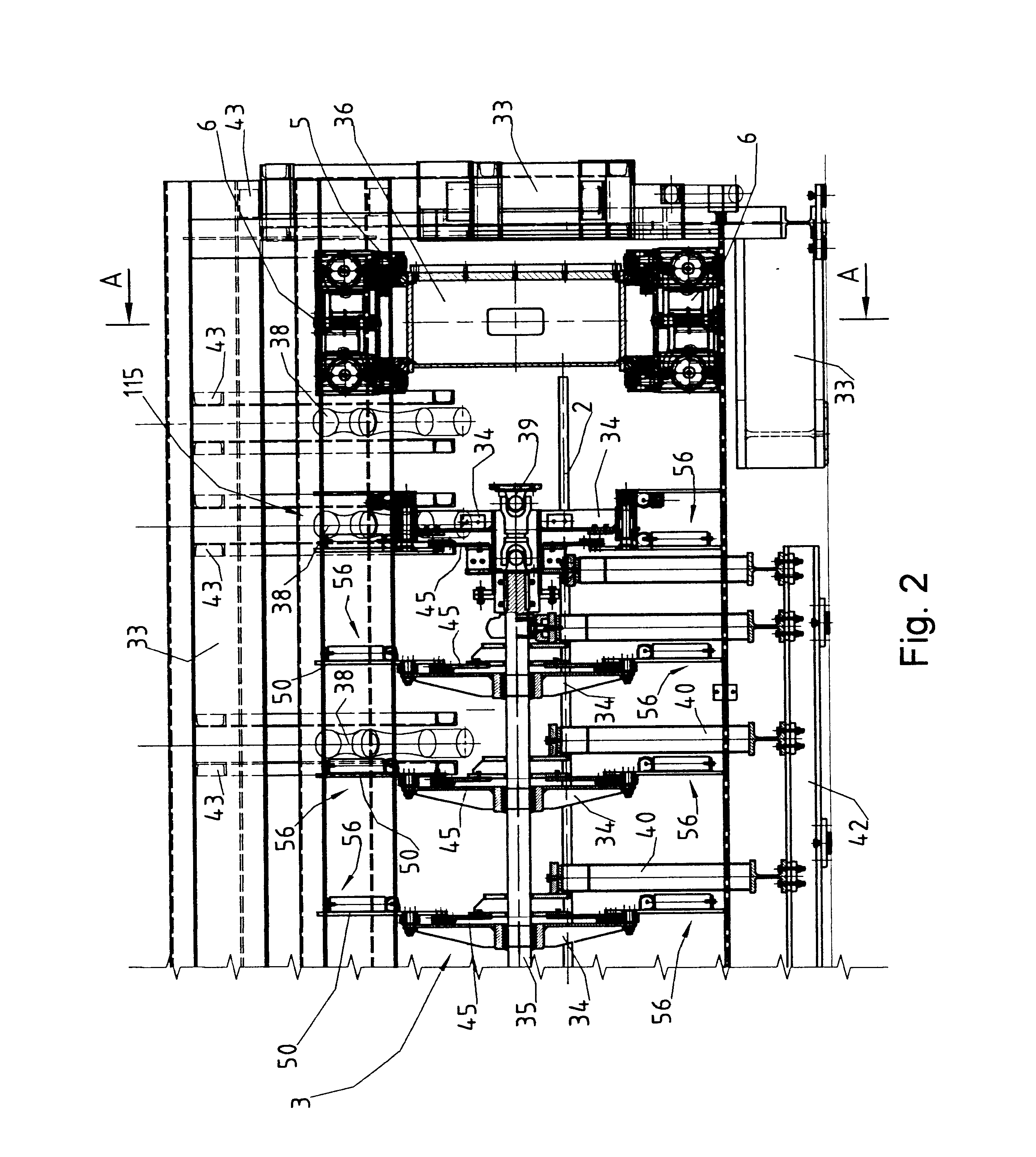
The entrance turnover device 3 structure is preferentially formed by the housing 33, rotating wheels 34 with girders 40, guiding plates 45, drive-shaft 35, Cardan joint 39, and bearing coupling 56, presented in FIG. 2 to FIG. 7 inclusive.

The endless conveying chain 5 with clamping units 6 and oblique...


PUM


Abstract

Machine for profile working of front surfaces on oblong wood workpieces resolves the problem of simple, accurate and fluent or continued working of workpieces front surfaces of various lengths and intersections, and the machine is of a compact construction. It is characteristic by the construction of the entrance turnover device transversely placed between longitudinal conveyors with carriers, which has on the periphery of rotating wheels constructed movable bearing couplings, and by them fixed guiding plates with the groove inside which there are movably inserted guided bearings of bearing couplings. In the area of the entrance turnover device there are placed under an optional angle the oblique roller conveyors, inside which there are flexibly and circularly movably inserted rolls. Between the longitudinal conveyors there is placed the endless conveying chain, which has to its entire extent fastened clamping units that have inside the fixed housing inserted the clamping mechanism, the operation of which is regulated by the control field and control indicator. Over the free corner of the longitudinal conveyor there runs the oblique conveyor with carriers tilted to the longitudinal conveyor. Between longitudinal conveyors there is transversely placed the exit turnover device, which has on the periphery of rotating wheels constructed movable bearing cranks, being through the chain connected with the control chain wheel and control panel, the guided bearing of which is movably inserted inside the channel guide fixed on the rotating wheels.

Description

The invention relates to a machine for profile working of front surfaces on oblong wood workpieces, and is preferentially a machine to produce toothed or wedge joints on front surfaces of oblong wood workpieces of various lengths and intersections for their later series joining, wherein the entrance and exit turnover device and oblique roller conveyor are integrated, while the conveying chain of adjacent longitudinal conveyors is equipped with movable clamping units.According to the international patent classification this invention belongs to B 27F 1 / 12, and additionally to B 27F 1 / 16, B 65 G 17 / 46, and to B 65G 47 / 22.There are quite some known solutions of machines or devices respectively for manufacturing of front surface toothed, wedge joints for series joining of oblong workpieces. According to the oldest known solution the wood workpieces move towards the working unit lineally, in their longitudinal axis direction, they are stopped in front of the working unit and clamped in t...

Claims


Application Information

Patent Timeline
Patent Type & Authority Patents(United States)
IPC IPC(8): B23Q7/03B27F1/16B27F1/00B27M3/00B27M1/08B27M1/00B65G17/00B65G47/00
CPCB23Q7/035B27F1/16B27M1/08B27M3/002
Inventor LEDINEK, PAVELLEDINEK, GREGOR
Owner LEDINEK PAVEL
Learn More