
Resorbable posterior spinal fusion system

a posterior spinal fusion and fusion system technology, applied in the field of medical implants, can solve the problems of debility and disability, back pain remains a major public health problem, and one or more vertebrae and/or one or more discs may become damaged and malfunction,

Inactive Publication Date: 2004-04-13
HOSPITAL FOR SPECIAL SURGERY +1
View PDF20 Cites 315 Cited by
  • Summary
  • Abstract
  • Description
  • Claims
  • Application Information

AI Technical Summary

Problems solved by technology

Back pain remains a major public health problem, especially among aged people.
Persistent and severe back pain often causes debility and disability, and this pain is closely associated with intervertebral disc abnormalities of the spine.
As a result of exertion, injury, illness, accident or abuse, one or more of the vertebrae and / or one or more discs may become damaged and malfunctional.
However, it is often necessary to remove at least a portion of the damaged and / or malfunctioning back component.
The additional surgery can increase the risk of infection and can reduce structural integrity at the donor site.
Furthermore, many patients complain of significant pain for several years after the surgery.
With this technique, once fusion occurred across and incorporating the bone osteogenic fusion device, the hardware used to maintain the stability of the spine became superfluous.
Nevertheless, some of the interbody fusion devices still have difficulty in achieving a complete fusion, at least without the aid of some additional stabilizing device, such as a rod or plate.
Moreover, some of the devices are not structurally strong enough to support the heavy loads and bending moments applied at certain levels of the spine, namely those in the lumbar spine.
Even with devices that do not have these difficulties, other less desirable characteristics exist.
The stress-shielding phenomenon relieves some or all of the load applied to the material to be fused, which can greatly increase the time for complete bone growth, or disturb the quality and density of the ultimately formed fusion mass.
A further difficulty encountered with many fusion implants is that the material of the implant is not radiolucent.
Since most fusion devices completely surround and contain the bone graft material housed within the cage, the developing fusion mass within the metal cage between the adjacent vertebrae cannot be seen under traditional radiographic visualizing techniques and only with the presence of image scatter with CT scans.
Thus, the spinal surgeon does not have a means to determine the progress of the fusion, and in some cases cannot ascertain whether the fusion was complete and successful.

Method used


Image

  • Resorbable posterior spinal fusion system
  • Resorbable posterior spinal fusion system
  • Resorbable posterior spinal fusion system

Examples


Embodiment Construction

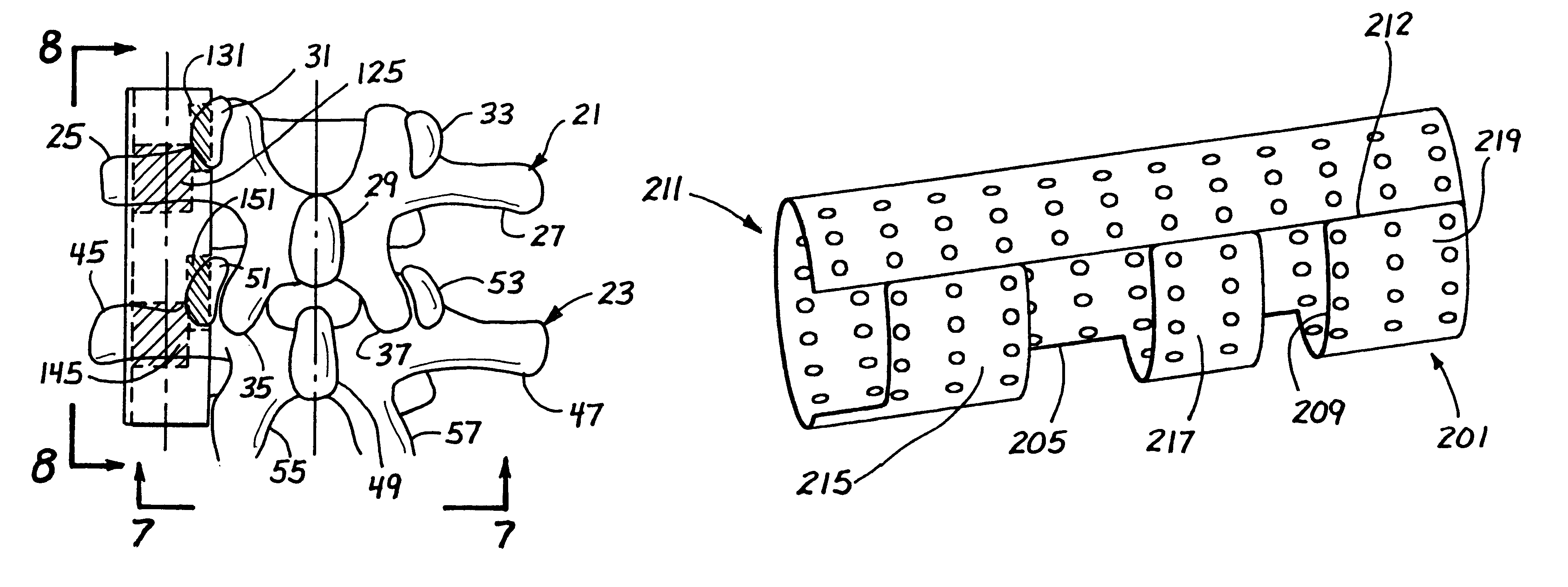
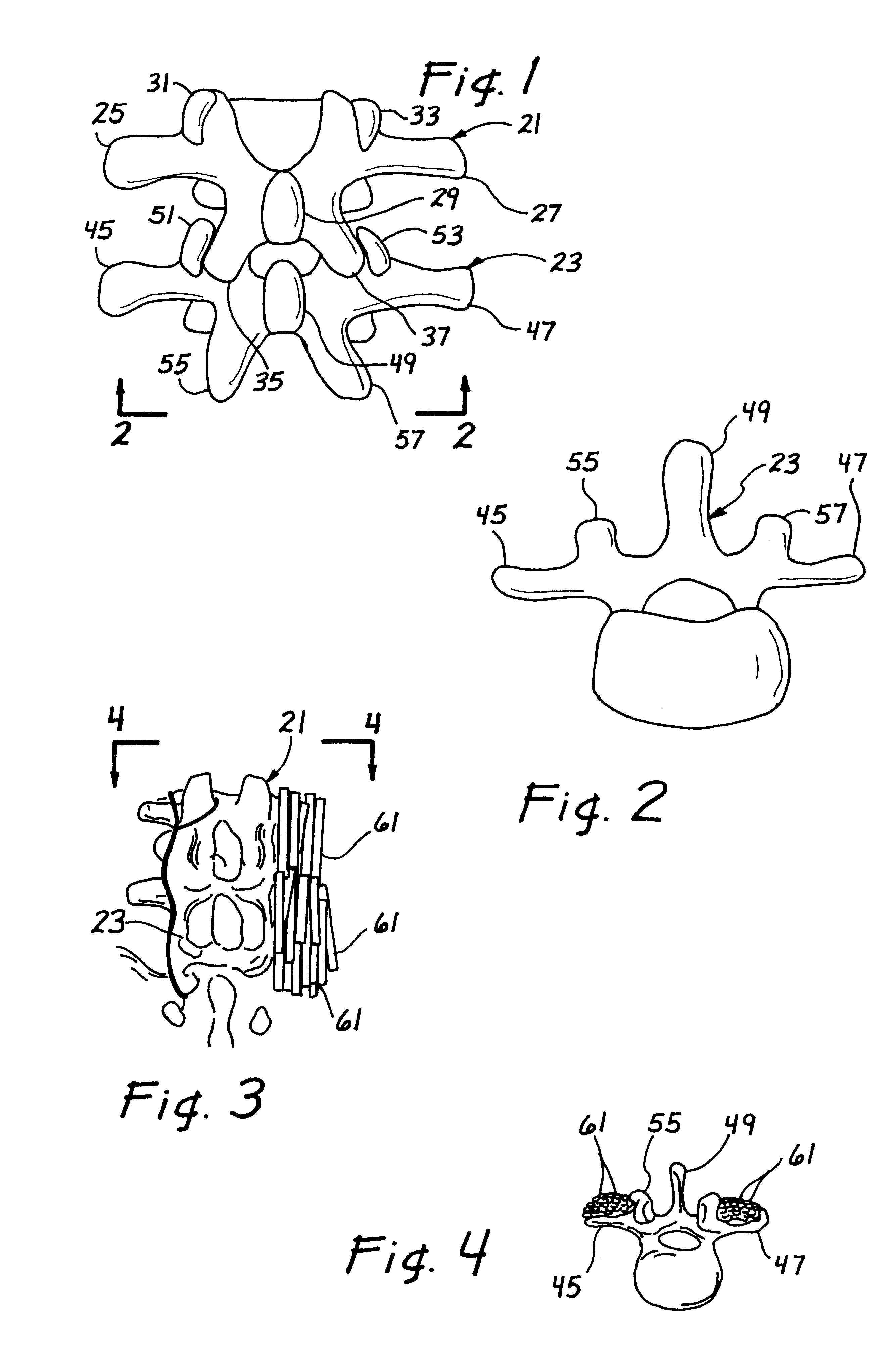
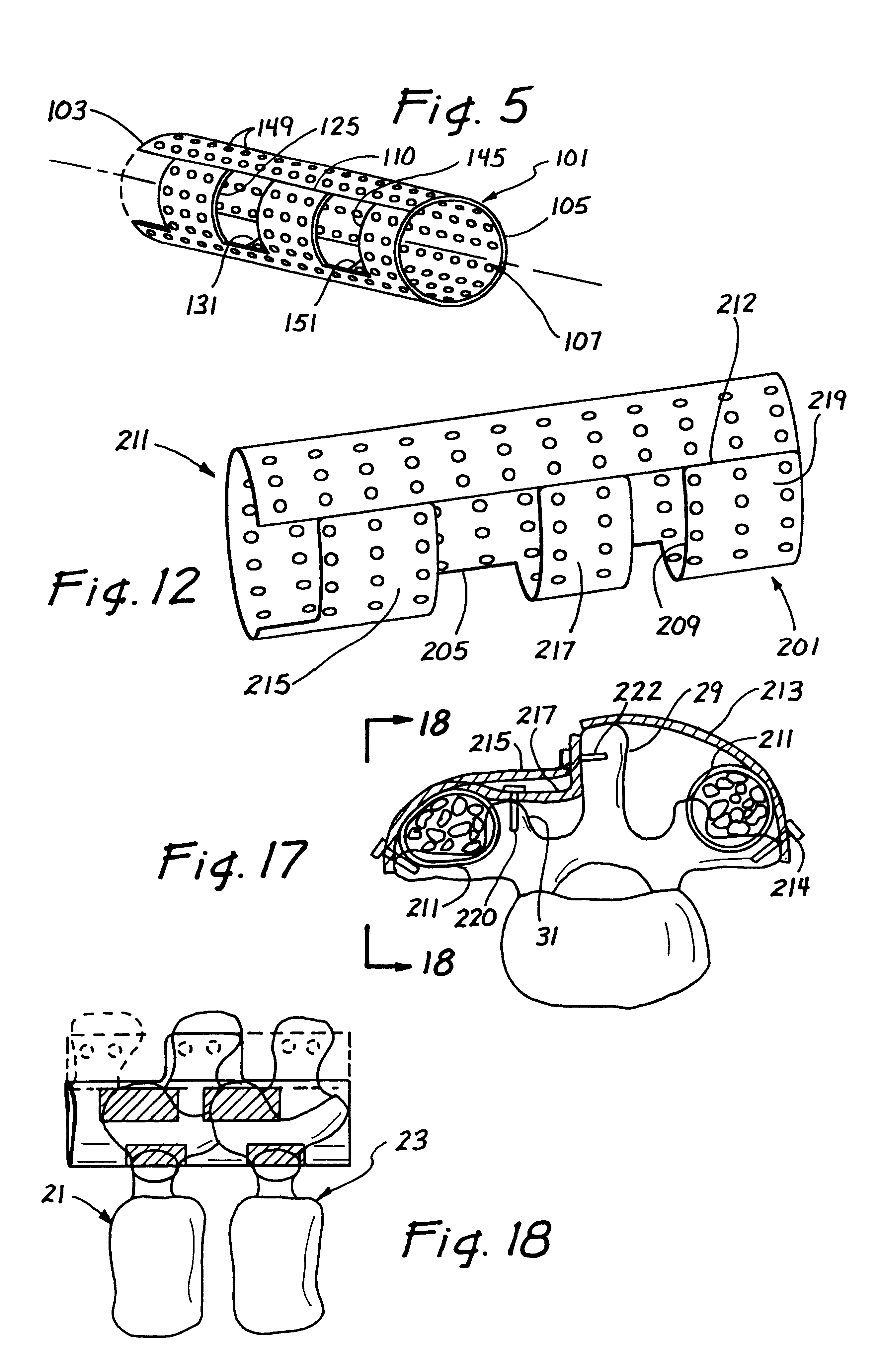
Turning to FIG. 5, a rolled resorbable membrane 101 is shown for facilitating posterior lateral fusion of at least two vertebrae. The rolled resorbable membrane 101 is sized and shaped to be placed into contact with at least two adjacent vertebrae and to facilitate osteogenic fusion between the vertebrae. As presently embodied, the rolled resorbable membrane 101 comprises a first end 103, a second end 105, and an axis 107 extending between the first end 103 and the second end 105. A lumen 107 extends along the length of the axis 107 between the first end 103 and the second end 105.

In the illustrated embodiment, the rolled resorbable membrane 101 is formed into a cylindrical shape wherein the first end 103 and the second end 105 are open to the lumen 107. This cylindrical shape may be achieved by providing a planar resorbable membrane and bringing two opposing edges together. In the embodiment of FIG. 5, a planar, rectangular resorbable membrane with four edges is wrapped around a ma...


PUM

PropertyMeasurementUnit
Timeaaaaaaaaaa
Thicknessaaaaaaaaaa
Thicknessaaaaaaaaaa

Abstract

Rolled resorbable membranes and methods for their application have been discovered. In accordance with one aspect of the present invention, rolled resorbable resorbable membranes are applied to the transverse processes of two or more vertebrae to facilitate fusion of the vertebrae.

Description

1. Field of the InventionThe present invention relates to medical implants and, more particularly, to medical implants for the correction of an unstable parts of the spine by joining two or more vertebrae.2. Description of Related ArtBack pain remains a major public health problem, especially among aged people. Persistent and severe back pain often causes debility and disability, and this pain is closely associated with intervertebral disc abnormalities of the spine.The human spine is a flexible structure comprised of thirty-three vertebrae. Intervertebral discs separate and cushion adjacent vertebrae, act as shock absorbers, and allow bending between the vertebrae. An intervertebral disc comprises two major components: the nucleus pulposus and the annulus fibrosis. The nucleus pulposus is centrally located in the disc and occupies 25-40% of the disc's total cross-sectional area. The annulus fibrosis surrounds the nucleus pulposus and resist torsional and bending force applied to th...

Claims


Application Information

Patent Timeline
IPC IPC(8): A61B17/80A61B17/70A61B17/68A61F2/30A61F2/28A61F2/02A61F2/00A61F2/44A61B17/00
CPCA61B17/707A61B17/8085A61B17/7032A61B2017/00004A61F2/2846A61F2/4455A61F2002/2817A61F2002/2835A61F2002/30062A61F2002/30293A61F2002/30785A61F2002/30787A61F2210/0004A61F2230/0091Y10S606/908Y10S606/91
Inventor CORNWALL, G. BRYANSOHNGEN, GARYLANE, JOSEPH M.TOMIN, EMRE A.
Owner HOSPITAL FOR SPECIAL SURGERY
Learn More