
Device and method for authorizing use of a pre-coded display area

a pre-coded display and device technology, applied in the field of display technology, can solve the problems of inability to use conventional window systems, inability to use processing units, and inability to allow multi-window display

Inactive Publication Date: 2004-03-23
PANASONIC CORP
View PDF10 Cites 58 Cited by
  • Summary
  • Abstract
  • Description
  • Claims
  • Application Information

AI Technical Summary

Benefits of technology

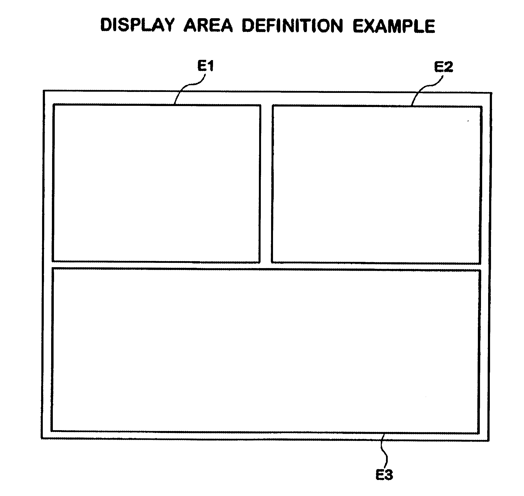
(1) A display control device and method according to the present invention defines a plurality of display areas in the display device, and when a display area acquisition request is received from each processing unit, it is decided whether to use the requested display area, and the processing unit which is allowed to use the display area can display data there. By defining display areas in advance, and by allowing the use of each display area, without leaving control to each processing unit, an appropriate display for each processing unit according to the applied equipment becomes possible. Also inappropriate display is prevented.
(16) When a request for a display area which cannot coexist is received, the display control device according to the present invention changes the display area based on dependency relationship information defining the changes of the display area to make coexistence possible. As a consequence, the display area can be quickly changed so as to make coexistence possible.
(19)(20) The display control device according to the present invention allows two or more processing units simultaneous use of one display area. As a consequence, it is possible to control so as to allow two or more processing units to use one display area.
(25)(26) The display control device according to the present invention assigns a key to the processing unit when use of a display area is allowed, and the display processing supervisory means supervises by judging whether the key shown by the processing unit is the correct key. As a consequence, invalid display processing can be easily supervised. By assigning a different key each time, invalid display processing using an old key can be prevented.

Problems solved by technology

When such a problem occurs, the user must change the position of the window which is overlapped by another window in order to view the display of the window, which is troublesome.
For such devices, a conventional window system cannot be used.
In other words, an undesired display of multi-windows is inevitable, and the above mentioned problems are not solved.
In accordance with the Japanese Laid-Open Patent Application HEI1-100662, the handling of overlapping windows also depends on the application, where an undesired display of multi-windows is still inevitable, and the above mentioned problems are not solved.
As a consequence, to make display efficient, use is not allowed for a processing unit which cannot actually execute display processing and processing related to display.
"Cannot coexist" is the case when displaying in a plurality of display areas is not desirable.
Depending on the equipment to which the display control device is applied to or depending on the status, a plurality of display areas may not be able to coexist if a part of the display area overlaps, or may be able to coexist even if overlapping exists in a predetermined allowable range.

Method used


Image

  • Device and method for authorizing use of a pre-coded display area
  • Device and method for authorizing use of a pre-coded display area
  • Device and method for authorizing use of a pre-coded display area

Examples


eighth embodiments

10. Eighth Embodiments

10.1 General Configuration

10.2 Example When One Processing Unit is Allocated to One Display Area

10.3 Example When a Plurality of Processing Units are Allocated to One Display Area

10.4 Example When a Plurality of Tasks are Allowed to Use One Display Area

1. Display Control Device in Accordance with the Basic Concept of the Invention

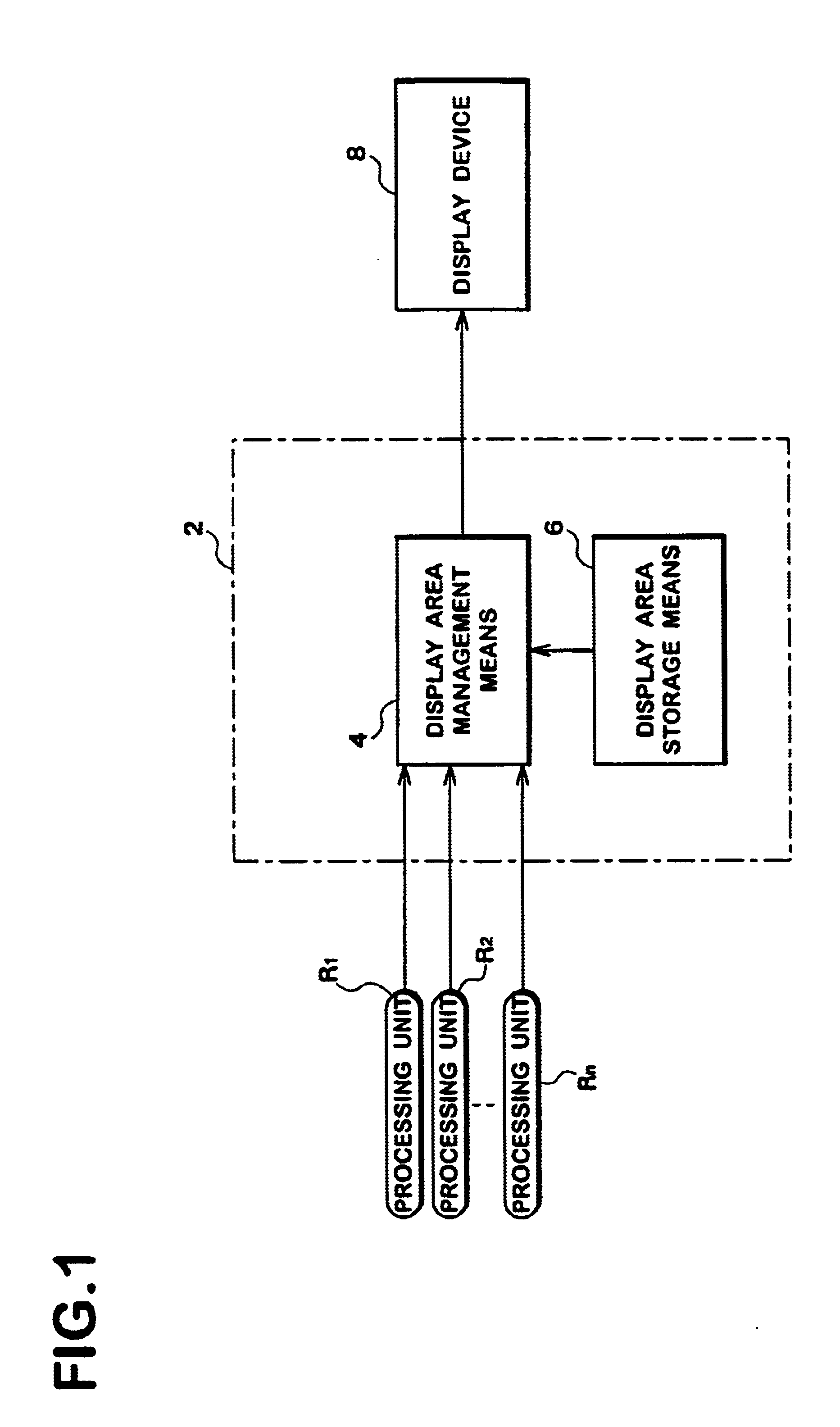
FIG. 1 shows a general configuration of the display control device 2 as an embodiment of the basic concept of the present invention. The display control device 2 comprises display area management means 4 and display area storage means 6. The display area storage means 6 stores definitions of a plurality of display areas which are set on a screen of the display device 8. To the display area management means 4, a display area acquisition request for displaying is sent from a plurality of processing units R1-Rn. The display area management means 4 decides whether use of the display area is allowed for each processing unit, considering the...

first embodiment

2. First Embodiment

2.1 General Configuration

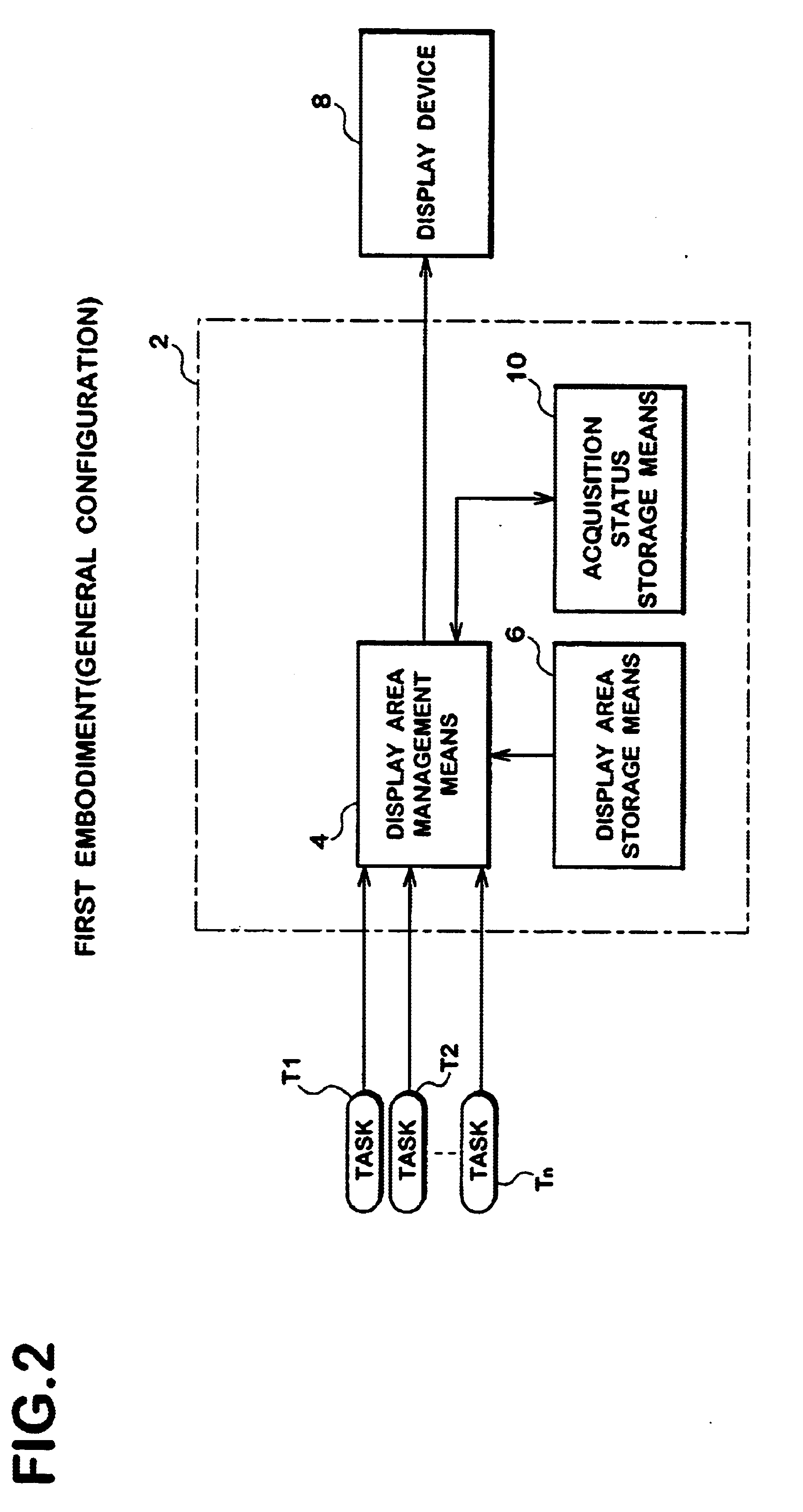
FIG. 2 shows a general configuration of a display control device 2 as an embodiment of the present invention. In this embodiment, acquisition status storage means 10 connected to the display area management means 4 is disposed. The acquisition status storage means 10 stores the acquisition status correlating a display area and tasks T1-Tn which are processing units which acquired the display area. When a display area acquisition request is received from one of the tasks T1-Tn, the display area management means 4 judges whether the display area has been acquired by another task based on the storage content of the acquisition status storage means 10. If the display area has been acquired by another task, the task is not allowed to use the display area. If the display area has not been acquired by another task, the task is allowed to use the display area.

2.2 Example of Application to Digital Broadcasting Receiver

FIG. 3 shows a hardware config...

second embodiment

3. Second Embodiment

3.1 General Configuration

FIG. 13 shows a general configuration of a display control device 2 according to the second embodiment of the present invention. In this embodiment, coexistence relationship storage means 20 is disposed. The coexistence relationship storage means 20 stores the coexistence relationship information to indicate whether a plurality of display areas can coexist. The display area management means 4 judges whether the display areas desired by the acquisition requests from each processing unit R1-Rn can coexist, based on the coexistence relationship information of the coexistence relationship storage means 20. If coexistence is impossible, the processing unit which requested acquisition first is allowed use of the display area.

A display processing supervisory means 22 judges whether each display processing by each processing unit R1 Rn is for a display area where use of each display processing is allowed. If the display processing is for a displa...


PUM


Abstract

The present invention provides a device and a method for displaying appropriately on the display area for each processing unit such as an application according to the applied equipment. The CPU 12 processes display area acquisition requests from a plurality of processing units R1-Rn according to a display management program. The display management program decides whether use of the display area is allowed to each processing unit, considering the relationship of the plurality of display areas requested from each processing unit R1-Rn. Each processing unit R1-Rn executes display processing for the display area for which use is allowed. In this way, whether use is allowed is notified from the display management program to each processing unit R1-Rn after each processing unit R1-Rn sends the display area acquisition request. As a consequence, display in a plurality of areas by each processing unit R1-Rn can be controlled appropriately.

Description

1. Field of the InventionThe present invention relates to a technology for control display on a screen by a plurality of processing units (tasks and applications), and more particularly to an allocation of the display area.2. Description of the Related ArtWhen a plurality of applications display on one screen, a window system, such as X-Window System, has been used. In these window systems, each application displays acquiring the respective window (multi-window).Japanese Laid-Open Patent Application HEI4-274289 discloses a device which groups windows acquired by each application, and displays or does not display in group units.Also in accordance with Japanese Patent Laid-Open No. 1-100662, when contents displayed on a plurality of windows are inter-related, these plurality of windows are simultaneously displayed so that the user can easily understand the display contents.However, with the conventional display based on a multi-window, what application displays on what display area ba...

Claims


Application Information

Patent Timeline
IPC IPC(8): G06F3/14G09G5/395G09G5/14G09G5/36G09G5/393G06F9/50G06F9/46H04N5/445H04N5/44G06F3/00G06F3/048G09G5/00G09G5/39H04N5/45H04N7/173H04N21/431H04N21/443H04N21/472H04N21/478H04N21/482H04N21/488
CPCG06F3/14G06F9/5011G09G5/001G09G5/14G09G5/39G09G5/393H04N5/44543H04N5/44591H04N21/4316H04N21/4438G09G2310/04G09G2340/02G09G2340/12G09G2340/125G09G2360/12H04N5/4401H04N21/47214H04N21/478H04N21/482H04N21/4882G06F2209/506H04N21/47H04N21/426G06F3/0481G06F2203/04803
Inventor SEKIGUCHI, TAKUYAYOSHII, TAKETOYASUTAKE, KOUICHIOKAMURA, KAZUO
Owner PANASONIC CORP
Learn More