
Temperature sensing circuit and method

a temperature sensing and circuit technology, applied in the field of sensing a temperature, can solve the problems of occupying an excessive amount of silicon space, affecting the ability to accurately measure temperature, and complex devices and/or circuitry for measuring the frequency of the ring oscillator and determining the temperature therefrom

Inactive Publication Date: 2004-02-24
STMICROELECTRONICS SRL
View PDF13 Cites 74 Cited by
  • Summary
  • Abstract
  • Description
  • Claims
  • Application Information

AI Technical Summary

Benefits of technology

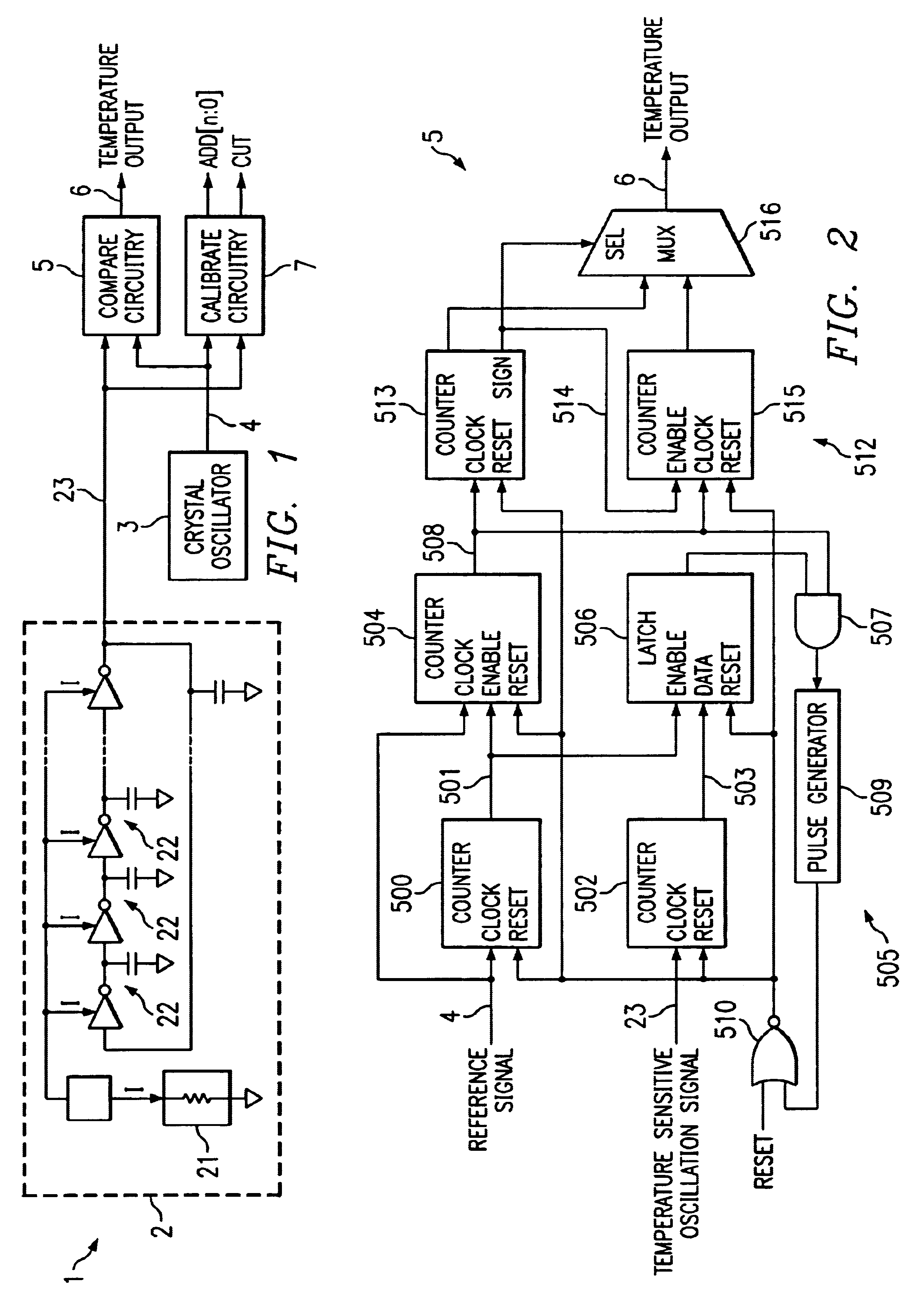
The present invention provides a temperature sensing device that can accurately and efficiently measure temperature. The device includes an oscillator circuit that generates a first signal having a frequency that is dependent upon the sensed temperature and a ring of logic inverters that operate at a current level dependent upon the resistance of a PTAT resistive element. The device also includes a self-calibration circuit for comparing the frequency of the first signal with a known, temperature-insensitive reference signal and generating one or more calibration output signals having a value indicative of an amount by which the PTAT resistive element needs to be increased or decreased. The invention addresses the shortcomings of conventional temperature sensing devices by providing a more efficient and accurate solution for measuring temperature.

Problems solved by technology

One shortcoming with conventional temperature sensors is that devices and / or circuitry for measuring the frequency of the ring oscillator and determining the temperature therefrom are oftentimes complex and occupy an excessive amount of silicon space.
This can be seen to adversely affect the ability to accurately measure temperature.

Method used


Image

  • Temperature sensing circuit and method
  • Temperature sensing circuit and method
  • Temperature sensing circuit and method

Examples


Embodiment Construction

The present invention will now be described more fully hereinafter with reference to the accompanying drawings in which preferred embodiments of the invention are shown. This invention may, however, be embodied in many different forms and should not be construed as being limited to the embodiments set forth herein. Rather, the embodiments are provided so that this disclosure will be thorough and complete, and will fully convey the scope of the invention to those skilled in the art.

Referring to FIGS. 1-6, there is shown an on-chip temperature sensing device 1 according to exemplary embodiments of the present invention. Temperature sensing device 1 senses a temperature and generates a signal indicative of the sensed temperature. Temperature sensing device 1 may be implemented as part of an integrated circuit chip performing other functions in addition to temperature sensing. Alternatively, temperature sensing device 1 may be implemented as a stand-alone integrated circuit.

Temperature ...


PUM

PropertyMeasurementUnit
temperatureaaaaaaaaaa
frequencyaaaaaaaaaa
absolute temperatureaaaaaaaaaa

Abstract

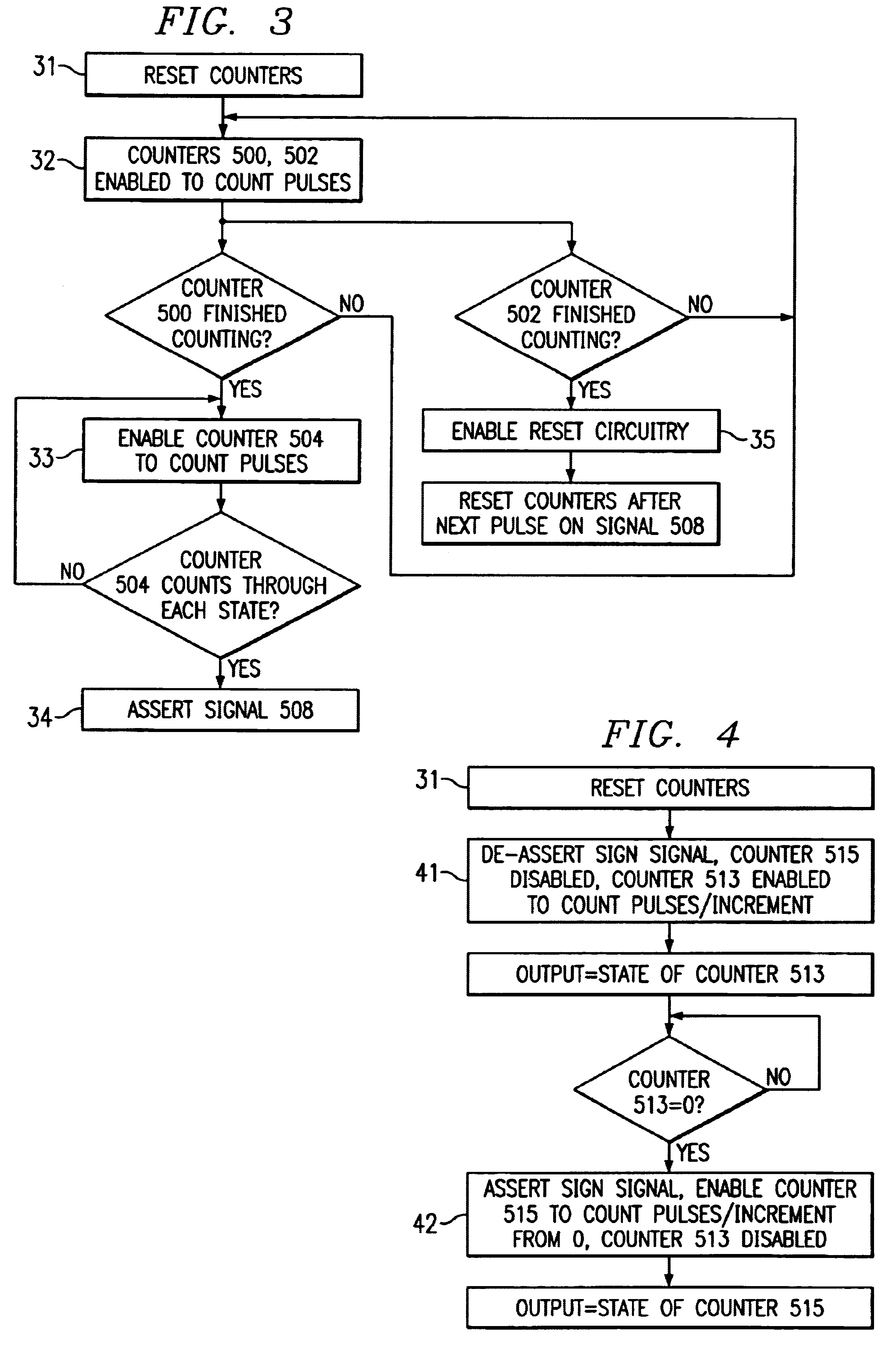
A method and circuit are disclosed for measuring temperature. An exemplary embodiment of the present invention includes a first oscillator circuit that generates a first signal having a frequency that is dependent upon a sensed temperature. Difference circuitry determines a difference in frequency between the first signal and the second signal having a frequency that is substantially independent of temperature, and generates a difference signal having a number of pulses thereon based upon the difference. A counter circuit is responsive to the difference circuitry for offsetting a predetermined temperature level based upon the pulses appearing on the difference signal, to obtain an output signal indicative of the sensed temperature.

Description

1. Technical Field of the InventionThe present invention relates to sensing a temperature, and particularly to a circuit and method for temperature sensing, with self-calibration.2. Description of the Related ArtOn-chip temperature sensors have been used in a variety of applications to measure temperature. A typical on-chip temperature sensor utilizes a proportional-to-absolute-temperature (PTAT) resistive element having a resistance that is based upon its temperature, and a ring oscillator which oscillates at a frequency that is dependent upon the resistance of the PTAT resistive element. The temperature is determined by measuring the frequency of the ring oscillator and determining the temperature sensed by the PTAT resistive element based upon the measured frequency.One shortcoming with conventional temperature sensors is that devices and / or circuitry for measuring the frequency of the ring oscillator and determining the temperature therefrom are oftentimes complex and occupy an ...

Claims


Application Information

Patent Timeline
Patent Type & Authority Patents(United States)
IPC IPC(8): G01K7/20G01K15/00G01K7/16
CPCG01K7/203G01K15/00
Inventor YIN, RONG
Owner STMICROELECTRONICS SRL
Learn More