
Data processing form for use with a scanning apparatus

a scanning apparatus and data processing technology, applied in the field of scanning apparatus forms, can solve the problems of inability to easily operate on other test forms, inconvenient use for users, and devices usually designed with limited versatility, so as to achieve the effect of adding versatility

Inactive Publication Date: 2004-02-24
APPERSON WILLIAM
View PDF7 Cites 8 Cited by
  • Summary
  • Abstract
  • Description
  • Claims
  • Application Information

AI Technical Summary

Benefits of technology

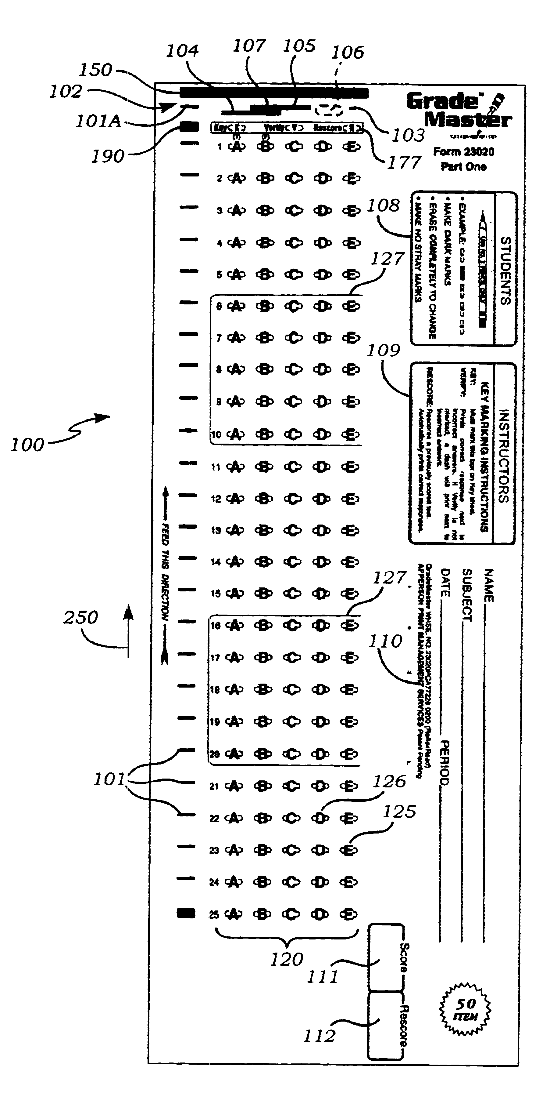
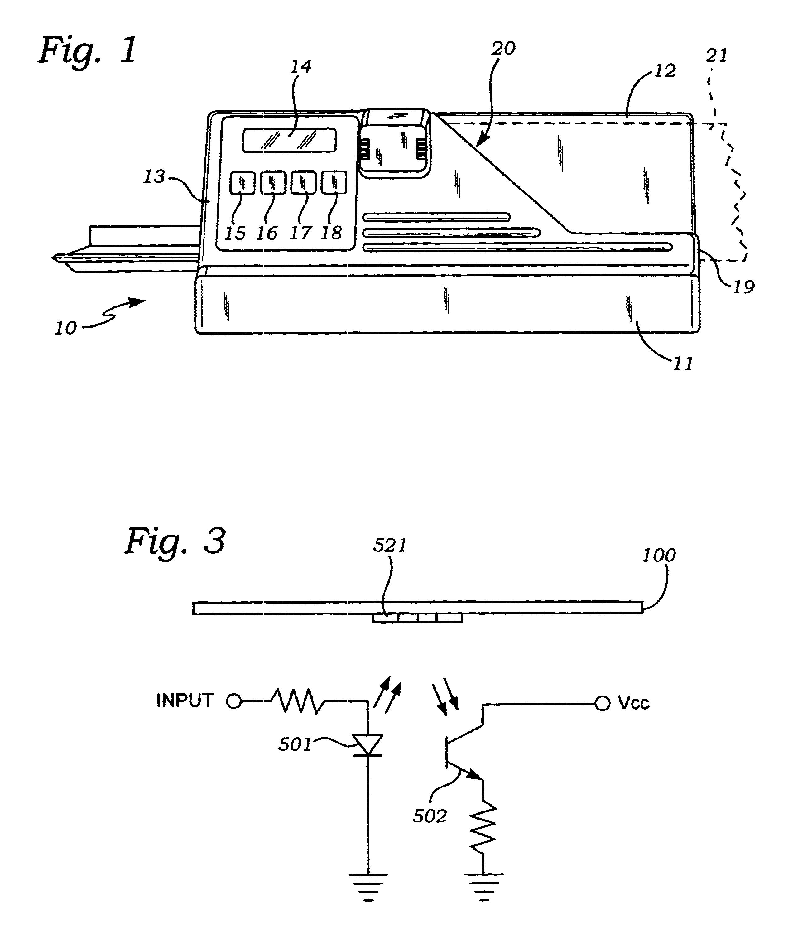
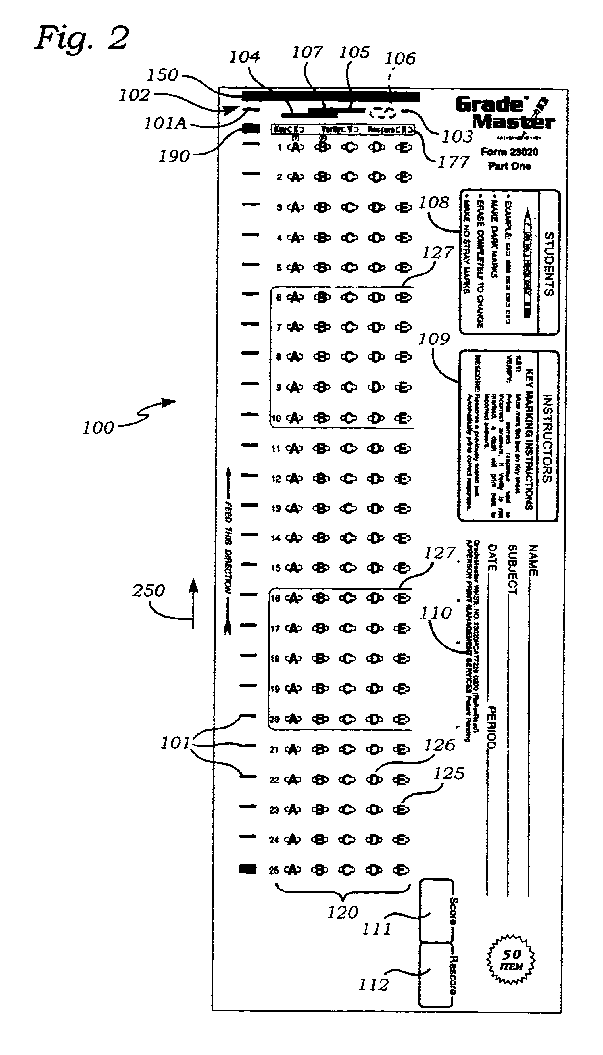
"This patent is about a scannable form that can be used with a scanner device. The form has graphic switches printed on it that can be used to define the characteristics of a test form. The switches use only black and white designations which are readily ascertainable by the scanner. This allows for a binary or quadruple interpretation of marks, which can assign values to the marks based on their position or level. The form is useful for grading student test forms, reading ballot forms for elections, and for reading forms designed for survey tabulation. The use of quad graphic switches adds versatility to the scanner and allows it to accept a multitude of test answer sheets without the need for costly reprogramming. The patent also includes a front perspective view of a representative scanner used with the invention and a schematic representation of a sensor utilized in the invention."

Problems solved by technology

If the skunk mark pattern for a form, typically a newly designed form, has not been programmed into these devices, the scanner will reject the form as unrecognizable.
These devices usually have been designed with limited versatility and do not easily operate on other test forms which are compatible, for example in size and shape, with the mode of operation thereof.
This lack of versatility is a significant inconvenience to the user who wishes to use a form which is not included in the specific "family" of forms that has been "pre-programmed" or designed to operate with the existing scanner.
This form is an excellent form but is somewhat limited in the number of distinct forms which can be identified by the three-level graphic switches.
This limited number of distinct forms allowed is particularly a problem when due to size and cost constraints the form can only have a limited number of graphic switches available.
The market also dictates that this device must be economical which forces cost limitations on the number of graphic switch settings that can be interpreted by the device.

Method used


Image

  • Data processing form for use with a scanning apparatus
  • Data processing form for use with a scanning apparatus
  • Data processing form for use with a scanning apparatus

Examples


Embodiment Construction

Referring now to FIG. 1, there is shown a front, perspective view of one type of scanner 10 which can read the forms of the instant invention. The scanner 10, which is typical only is described only as representative and is not limitative of the invention. Any suitable scanner can be utilized. The illustrative scanner includes a base 11, a back support 12 and a housing 13. The back support 12 is used, inter alia, to support a form or document 21 (shown dashed) which is to be scanned by the system.

A channel 19 is formed between the base 11 and the back support 12 to receive an edge of the form 21. A slot 20 is formed between the back support 12 and the housing 13 so that the form 21 can be passed therethrough adjacent to the scanning mechanism described hereinafter. A display 14 of any suitable type, such as light emitting diodes (LED's) or the like is used to provide information to the user, as described hereinafter. In addition, the control buttons 15, 16 and 17 are used to cause t...


PUM


Abstract

This invention is directed to a unique type of form to be used with an optical mark sensing device known as a mark read scanner for reading marks on the form. Form characteristics are defined by "graphic switches" printed near the lead edge of the form. Each "graphic switch" has four distinct settings. The expense of completely replacing the internal program of a scanner when a user requests a variation of a test form that had not been pre-programmed into the original specification of the scanner is eliminated.

Description

1. Field of the InventionThis invention relates to a form for use with an optical mark sensing device, in general, and to a form which has specifically designed graphic switches on the forms, in particular.2. Prior ArtMark read scanners are used in a variety of data collection applications. The forms used with mark read scanners are commonly referred to as "bubble" or optical mark read (OMR) forms on which the user fills in a bubble (or space) on the form, typically, with a number 2 lead pencil.Most known mark sensory and scoring devices and mark interpretation software use a binary system for describing the absence or presence of a mark. These systems are limited to the presence / absence or on / off binary sequence. Thus, very large numbers of codes are needed in order to read a relatively large number of marks. Mark positions on forms known in the art are, typically, assigned digital values between "0" and "255" at the start of the process. These values are often refined to 16 levels...

Claims


Application Information

Patent Timeline
Patent Type & Authority Patents(United States)
IPC IPC(8): G06K17/00
CPCG06K17/0032
Inventor APPERSON, WILLIAM
Owner APPERSON WILLIAM
Learn More