
Reproduction of spatialized audio

Inactive Publication Date: 2004-02-17
BRITISH TELECOMM PLC
View PDF5 Cites 68 Cited by
  • Summary
  • Abstract
  • Description
  • Claims
  • Application Information

AI Technical Summary

Problems solved by technology

However, ambisonic technology has its limitations when used in telepresence environments, as will be discussed.
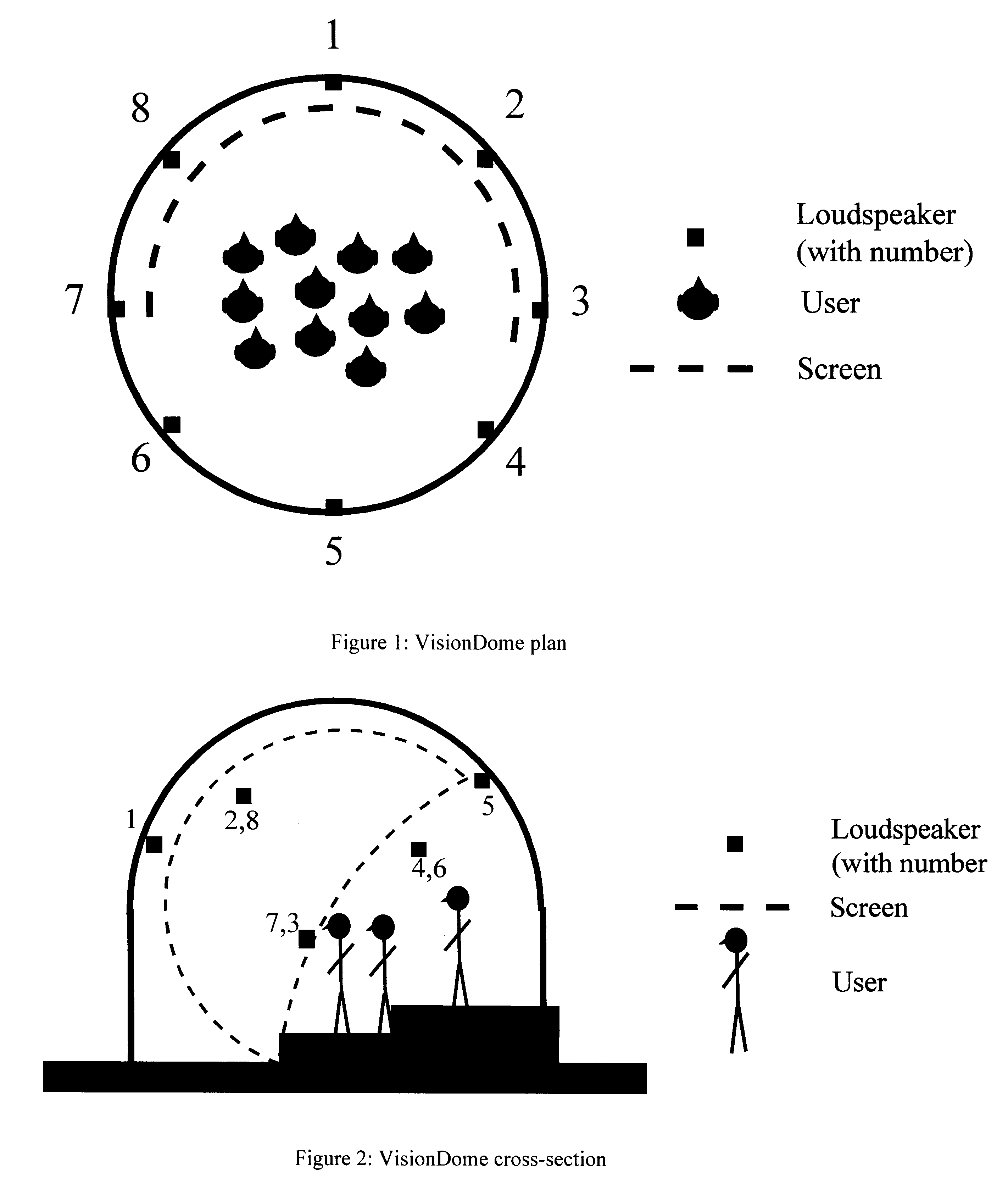
When replayed in a hemispherical dome, spatialisation is impaired by the geometry of the listening environment.
Reflections within the hemisphere can destroy the sound-field recombination: although this can sometimes be minimised by treating the wall surfaces with a suitable absorptive material, this may not always be practical.
The use of a hard plastic dome as a listening room creates many acoustic problems mainly caused by multiple reflections.
The acoustic properties of the dome, if left untreated, cause sounds to seem as if they originate from multiple sources and thus the intended sound spatialisation effect is destroyed.
The material of the video screen itself is sound absorbent, so it assists in the reduction of sound reflections but it also causes considerable high-frequency attenuation to sounds originating from loudspeakers located behind the screen.
Listening environments other than a plastic dome have their own acoustic properties and in most cases reflections will be a cause of error.
However, the geometry of the audio effect is no longer consistent with the video and a non-linear mapping is required to restore the perceptual synchronisation.
In environments where a group of listeners are situated in a small area an ambisonic reproduction system is likely to fail to produce the desired auditory spatialisation for most of them.
However, this system is designed only for single users as the sweet-spot can only be moved to one position at a time.

Method used


Image

  • Reproduction of spatialized audio
  • Reproduction of spatialized audio
  • Reproduction of spatialized audio

Examples


Embodiment Construction

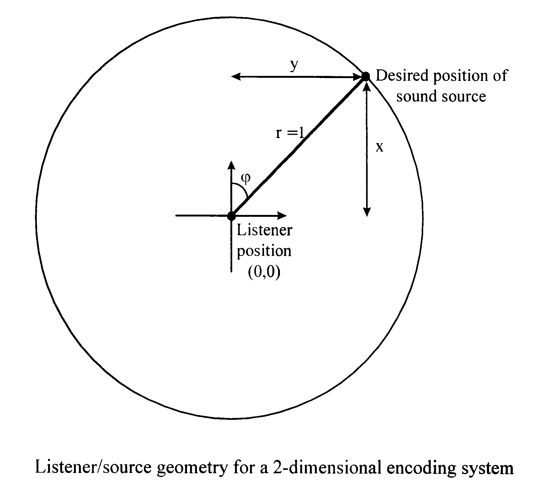
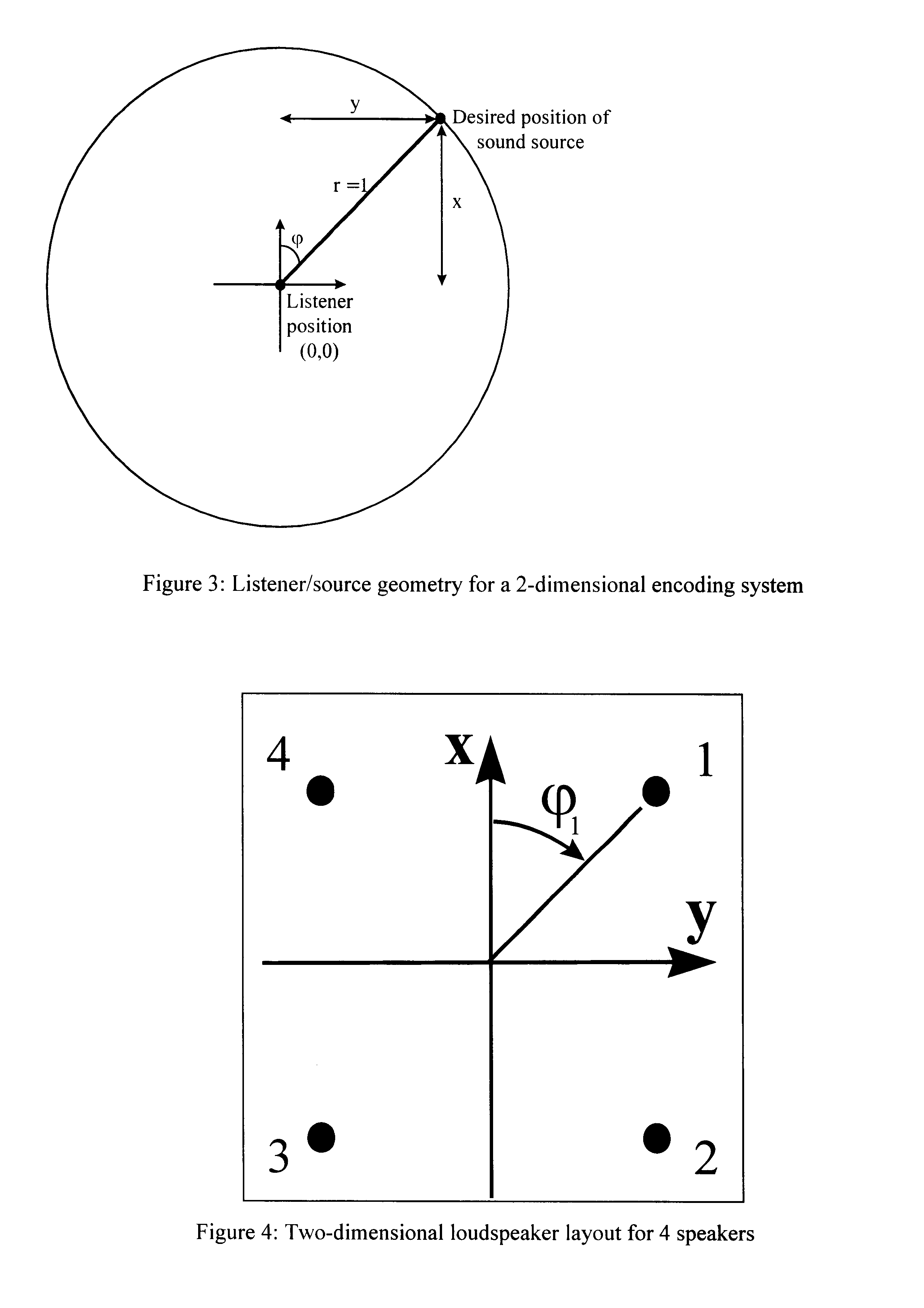
With a two-dimensional system the encoded spatialised sound is in one plane only, the (x,y) plane. Assume that the sound source is positioned inside a unit circle, i.e. x.sup.2 +y.sup.2.ltoreq.1 (see FIG. 3). For a monophonic signal positioned on the unit circle:

x=cos(.phi.)

y=sin(.phi.)

where .phi. is the angle between the origin and the desired position of the sound source, as defined in FIG. 3.

The B-Format signal comprises three signals W,X,Y, which are defined (see the Malham and Myatt reference above) as: ##EQU1##

X=S.multidot.cos(.phi.)

Y=S.multidot.sin(.phi.)

Where S is the monophonic signal to be spatialised.

When the virtual sound source is on the unit circle; x=cos(.phi.) and y=sin(.phi.), hence giving equations for W,X,Y in terms of x & y: ##EQU2##

X=x.multidot.S Front-Back signal

Y=y.multidot.S Left-Right signal

As also described by Malham and Myatt, the Decoder operates as follows. For a regular array of N speakers the pantophonic system decoding equation is: ##EQU3##

where .phi....


PUM


Abstract

Immersive environments for teleconferencing, collaborative shared spaces and entertainment require spatial audio. Such environments may have non-ideal sound reproduction conditions (loudspeaker positioning, listener placement or listening room geometry) where wavefront-synthesis techniques, such as ambisonics, will not give listeners the correct audio spatialization. A method disclosed for generating a sound field from a spatialized original audio signal, wherein the original signal is configured to produce an optimal sound percept at one predetermined ideal location. A plurality of output signal components are generated, each for reproduction by one of an array of loudspeakers. Antiphase output components are attenuated such that their contribution to the spatial sound percept is reduced for locations other than the predetermined ideal location. Position components defining the location of a virtual sound source, normalized to the loudspeaker distance from the ideal location, can be adapted to generate a warped sound field by raising the position components to a power greater than unity, such that the virtual sound source is perceived by listeners in the region surrounded by the loudspeakers to be spaced from the loudspeaker.

Description

1. Field of the InventionThis invention relates to the reproduction of spatialised audio in immersive environments with non-ideal acoustic conditions.2. Related ArtImmersive environments are expected to be an important component of future communication systems. An immersive environment is one in which the user is given the sensation of being located within an environment depicted by the system, rather than observing it from the exterior as he would with a conventional flat screen such as a television. This "immersion" allows the user to be more fully involved with the subject material. For the visual sense, an immersive environment can be created by arranging that the whole of the user's field of vision is occupied with a visual presentation giving an impression of three dimensionality and allowing the user to perceive complex geometry.For the immersive effect to be realistic, the user must receive appropriate inputs to all the senses which contribute to the effect. In particular, t...

Claims


Application Information

Patent Timeline
IPC IPC(8): H04S3/00
CPCH04S3/00H04S2420/11
Inventor RIMELL, ANDREWHOLLIER, MICHAEL PETER
Owner BRITISH TELECOMM PLC
Learn More