Eureka AIR delivers breakthrough ideas for toughest innovation challenges, trusted by R&D personnel around the world.

Control and display device

Inactive Publication Date: 2003-12-16
TESTO AG
View PDF23 Cites 183 Cited by
  • Summary
  • Abstract
  • Description
  • Claims
  • Application Information

AI Technical Summary

Benefits of technology

The present invention is based on the idea of integrating previously used multi-part additional protective housings into essentially one housing for a measuring instrument. This measuring instrument therefore includes a single, impact-resistant and water-tight housing, which may be a fixed component of this measuring instrument. Advantages of this measuring instrument, compared with known, two-part or multi-part, measuring instruments that require a water-tight housing (holster, shield) for use in wet environments, include low manufacturing costs.
The sealing effect in the area of an opening may be ensured by matching the shape and size of the opening to the shape and size of the plug, so that the housing is in contact with the plug over the entire surface of the latter and thus in a water-tight manner. In another embodiment, a sealing lip is provided in the opening, which is in a linear peripheral contact with the plug passing through it, thus providing a water-tight seal. This variant has the advantage that the plug may be inserted in the opening using little force. The opening may be closed with an appropriate cap when no plug is used.

Problems solved by technology

The functionality of such protective sheathings may be reduced over time due to the rough operating conditions to which the measuring instruments may be exposed.
Under extreme operating conditions, there is also the danger that the instrument may become damaged due to the effect of external forces, since the thin protective sheathing may be extremely sensitive to impact and forces.
In other words, the protective sheathings may not be able to absorb such forces thereby possibly resulting in damage to the instrument.
Another disadvantage of these known protective sheathings is the fact that even the slightest damage to the protective sheathing surface may result in impairing the required water-tightness.
This may subsequently irreversibly damage or destroy an electronic component that may be included in the instrument, and may be sensitive to moisture.
Furthermore, once the instrument is in the protective sheathing, it cannot be attached to a bracket provided, and external components cannot be attached to the instrument.
Although the protective device designed as a non-deformable shield and the protective housing designed as a holster have a high degree of water-tightness when used with a control and display device, providing protection against the effect of outside forces, there may still remain problems and drawbacks.
Manufacturing costs may be substantially increased since the measuring instruments to be used in the aforementioned areas requires an additional protective housing.
Even in this case, it is not possible to use a shield made of a very soft material, for example, a plastic, since such material does not have the rigidity required to obtain an effective seal or, alternatively may have this property only under certain conditions.
This may be, however, unacceptable due to the high cost involved.
This may be very expensive especially when a tight seal is required.
Therefore, often a plurality of support points, for example, screws or clamps, may be required and may result in an inability to obtain the required high degree of tightness.
In particular, when the screws are frequently removed from the measuring instruments, this gap-free seal becomes more and more difficult to guarantee.
Undesirable tolerances and slack may be poorly compensated for, or not at all, when the shield is mounted on the measuring instruments due to the close geometric relationship between the shield and the measuring instrument.
Failure to use such a protective housing in the aforementioned cases for reasons of time or convenience or due to lack of tools for fastening the fastening means may occur, and the measuring instrument used may not be able to be cleaned in a convenient and, mainly, reliable manner in a cleaning machine.
However, complete, one-hundred-percent cleaning cannot be assured with these cleaning procedures.
Since sealing occurs perpendicularly to the direction of joining with almost no force, no fastening elements such as screws or clamps are required here, which may reduce development and manufacturing time, sealing surfaces and therefore fastening material and sealing material costs.

Method used


Image

  • Control and display device
  • Control and display device
  • Control and display device

Examples


first embodiment

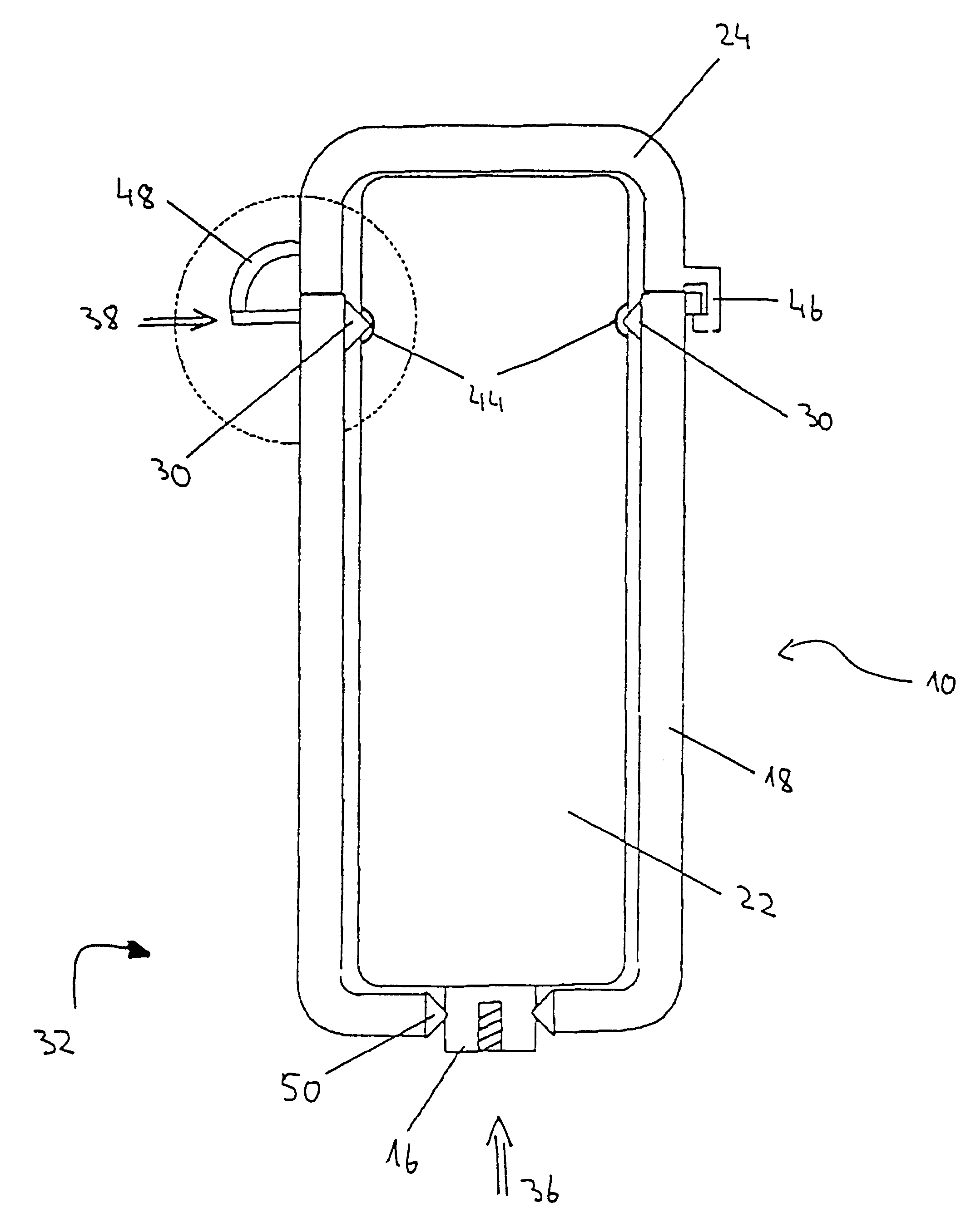
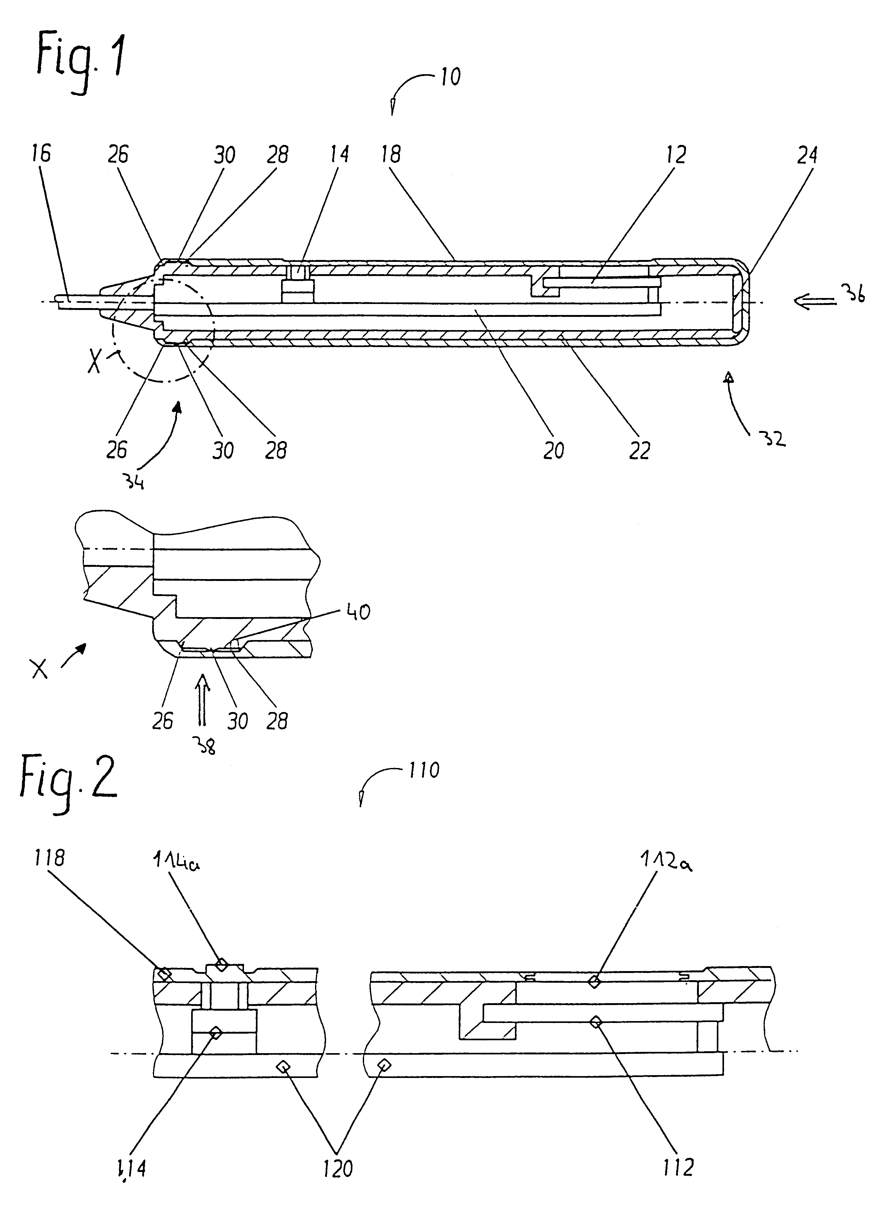
Referring to FIG. 1, shown is an example of a cross-section of a measuring instrument 10. Instrument 10 has, in the embodiment illustrated, a single housing 18, which has an essentially U-shaped cross section and accommodates an also essentially U-shaped sleeve 22 so that the end of sleeve 22, open on one side, is located on base 32 of housing 18. The end of sleeve 22, open on one side, is closed by a cover 24. A measuring sensor 16 protrudes from sleeve 22 on the side of sleeve 22 facing away from cover 24 and base 32. In the present embodiment, sensor 16 is designed as a probe tube for temperature measurement, but sensor 16 may also be designed in any other manner, for example, as a hygrometer probe, ampere meter, ohmmeter, pressure gauge probe, and the like.

A circuit board 20 having an indicator panel 12 and coupled to a keyboard 14 via contact-sensitive areas on circuit board 20, is provided within sleeve 22.

Indicator panel 12 may be designed as a display, for example, which is ...

second embodiment

FIG. 2 is an example of a cross section of details of an embodiment of an indicator area and a keyboard area of a measuring instrument. The same reference symbols, increased by 100, are used for the same elements and parts or those having the same function as in FIG. 1.

Instrument 110, shown in partial cross section in FIG. 2, also includes a housing 118, having an indicator panel 112, a keyboard 114, a circuit board 120, and a sleeve 122. Housing 118 has, in the area of the control panel, push rods 114a, each of which is assigned to a key of keyboard 114. These push rods 114a raise over the outer area of housing 118. In order to ensure simple actuation of keyboard 114, housing 118 in this embodiment may have, in the area of keyboard 114, i.e., at the edge of push rods 114a, a reduced wall thickness, so that this area of housing 118 can be easily elastically deformed, for example, with a finger tip or a rod for actuating the keys.

In contrast to the first embodiment according to FIG. ...

third embodiment

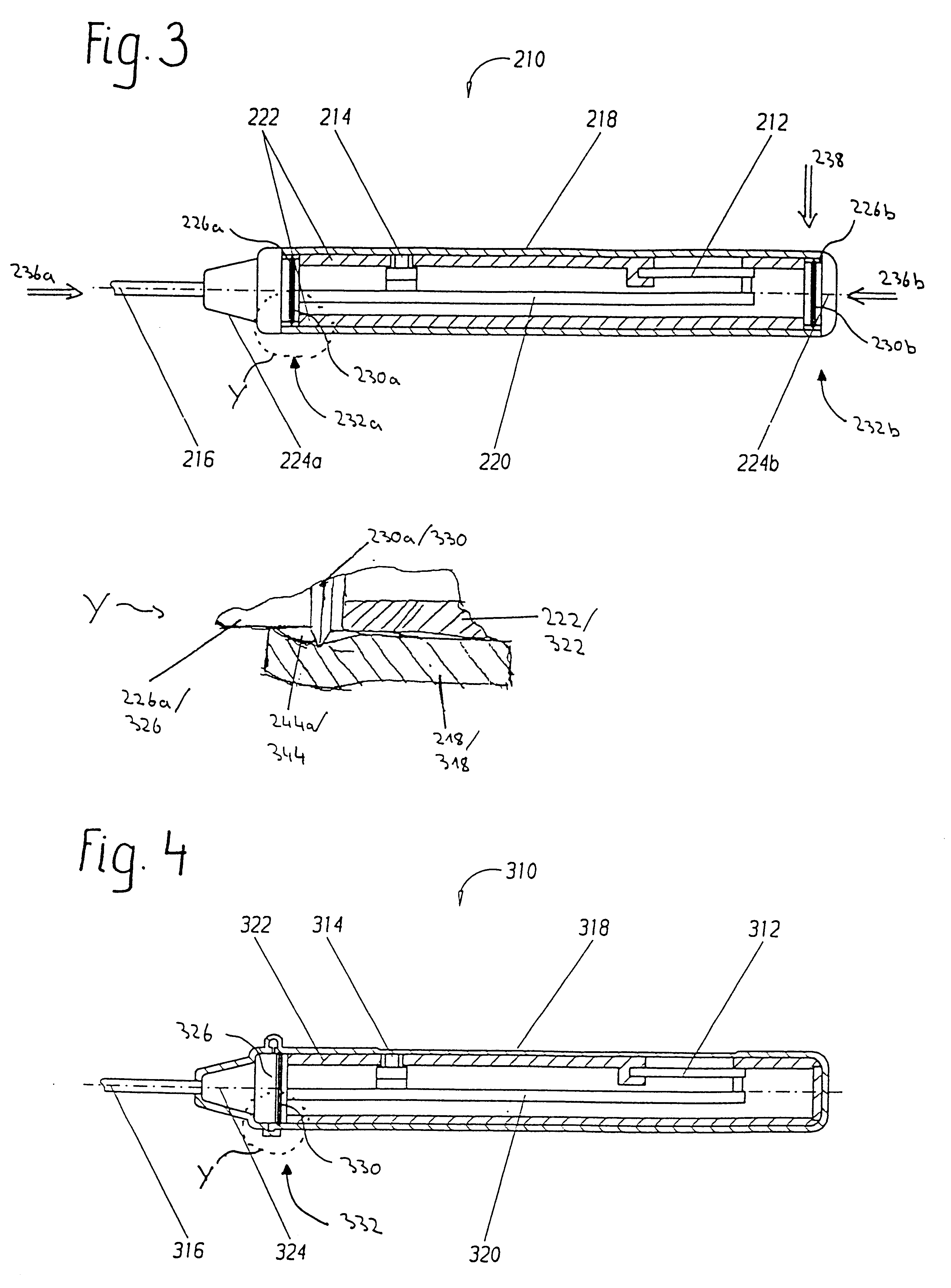
FIG. 3 is an example of measuring instrument 210. Identical element and parts or those having identical functions, are identified by reference numbers increased by 200 compared to those of FIG. 1.

With respect to the previously described embodiments set forth herein, a difference with reference to the embodiment of FIG. 3 is that housing 218 is provided with open end faces 232a, 232b arranged opposite each other. Each of these end faces 232a, 232b may be closed by a cover, respectively, 224a, 224b. A sensor 216 may be arranged on one of these covers, such as 224a, for example. Furthermore, this measuring instrument 210 may also include the above-described components, namely an indicator panel 212, a keyboard 214, a circuit board 220, and a sleeve 222.

In FIG. 3, end areas 232a, 232b of housing 218 are sealed via sealing devices. The sealing devices, which here seal housing 218 at the two covers 224a, 224b, may include a fixed ring 226a, 226b, which are also attached to a cover 224a, 2...


PUM


Abstract

A portable electrical control and display device is described, having an indicator panel, a keyboard with at least one key pad, and a single housing designed as a single piece and made of a temperature-resistant material, which seals the control and display device in a water-tight manner.

Description

1. Technical FieldThis application relates to a control and display device and, in particular, to a protective covering for the device.2. Description of Related ArtDevices, such as portable control and display devices, are generally known in a plurality of embodiments, for example, as measuring instruments. These instruments may be used in the food industry and in food processing plants such as, for example, slaughterhouses, refrigeration plants, restaurants, and the like. Instruments that may be used, for example, in the food industry and in areas related to food processing, may be required to comply with certain hygienic requirements and other regulatory requirements such as those set forth in national and international regulations. These requirements may relate to the cleanliness of the instruments, such as measuring instruments. The requirements may relate to, for example, prevention of contamination, such as, bacterial contamination, of the measuring instruments.In order to avo...

Claims


Application Information

Patent Timeline
IPC IPC(8): G01D11/24G01K13/00G06F3/02
CPCG01K13/002G01D11/24G01K13/20
Inventor DERR, ANDREASZAHN, PATRICK
Owner TESTO AG
Why Eureka
Eureka Blog
Learn More